I would definitely go up to 560R for the cathode resistor, and run the amp up on a variac just to make sure everything's ok.I've, finally, made my mind up and gone with Genelex Gold Lion KT66's.
Could I please just double check that I won't have to make any adjustments to the Cathode Resistor, which is 500R at present, with a plate voltage of 425v?
Sorry to be a pain just a quick double check, the KT88 i used previously was at 82mA which was running very close to 90%%, quite hot and I'd like to cool things down a little.
jeff
Thank you Jeff,I would definitely go up to 560R for the cathode resistor, and run the amp up on a variac just to make sure everything's ok.
560R it is, I don't have a variac so I'll try to get the drop voltage as close to switch on as possible. Not ideal, but should be OK.
(I think 🙏).
Maybe, start with a 680R?
Of course, all comments taken in good faith and any actions and consequences are taken entirely at my own risk.
Will await delivery, and will let you all know how it goes...
Will await delivery, and will let you all know how it goes...

Hi Hector,If you also get a 4.7K resistor, then you can tack it in parallel with the 560R to get back to 500R, should you want to. Even make it switchable.
Thank you for your advice. I've ordered a 560R and already have a new 500R. So, if I stick with KT66 I will leave the 560R or replace it with the 500R if I go back to KT88.
Should recieve the valves in a few days or so...
Hi all,
It's been a few months since last Post and have only just completed the amp, then, after checking everything, started testing.
I know a few basics, such as plate voltage, from my KT88 measures (425v plate), and using Rob Robinettes tube bias calculator, worked out that I should be looking at a cathode voltage drop of around 33v which would give me a plate-to-voltage of 392v and a KT66 plate dissapation 86%.
So, I connected my DMM to ground and to the + of the 570ohm cathode resistor and switched on.
The voltage steadily creeped up, kept creeping, and then went past 33v, I think I switched it of at around 40v which would mean plate dissapation is exceeding 100%.
I've checked, or think I have, everything, could anyone point me in the right direction or have any suggestions please?
It would be very much appreciated.
Not sure if you posted a schematic.
But Vk in itself is meaningless, for the tube what matters is Vgk.
You should verify if, with no signal, Vg is what it is supposed to be.
Is there a bias on the grid, or is it grounded through a resistor?
Check that resister value and make sure it really is connected to ground (or to the grid bias).
A quick B+ check would also be useful.
Schematic?
Jan
Hi Jan,
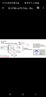
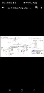
Thank you for the reply. Schematic attached from the excellent blueglow website, the circuit is common but I'm posting Blueglows artwork so I hope that is OK with everyone.
B+ is 436v and 425v on pin 3.
Only difference with mine is the cathode bypass cap which is 570R.
Thank you for the reply. Schematic attached from the excellent blueglow website, the circuit is common but I'm posting Blueglows artwork so I hope that is OK with everyone.
B+ is 436v and 425v on pin 3.
Only difference with mine is the cathode bypass cap which is 570R.
Attachments
Last edited:
570 ohm bypass? Are you referring to Rk or to the bypass cap?
Anyway, 41V across 500R is 82mA which with 450V B+ is 409 * 82 = 33.5W Pa.
If that is not what ypou want, I recommend to look at the tube Ia curves and look up the Vgk for your desired Ia with the B+ you have and size Rk accordingly.
Or just increase Rk until you have the Ia you want (which of course can be calculated from the voltage drop across Rk).
Edit: if Rk is 570R then of course Ia is about 72mA which gives 29W Pa.
Jan
Last edited:
41v across 500R amd 450v B+ is for that schematic using KT88 Jan.
Mine differs in that it has a B+ of 436v (425v on pin 3) and uses a KT66. Cathode resistor is 570R with 220uf bypass cap.
Mine differs in that it has a B+ of 436v (425v on pin 3) and uses a KT66. Cathode resistor is 570R with 220uf bypass cap.
Just testing B+ and that went quickly over 510v (!)
Also, there is no difference in voltage between B+ (460v on schematic) and + of the 33uf cap (442v on schematic).
Mine has the same measurement at B+ and at the cap (no drop at all)
Also, there is no difference in voltage between B+ (460v on schematic) and + of the 33uf cap (442v on schematic).
Mine has the same measurement at B+ and at the cap (no drop at all)
If you have no voltage drop across the 4.7K ('10') that means no current draw by the input stage. Check that Rk voltage drop.
Is that OK?
BTW Can you do those basic calculations yourself?
Jan
425V on A and 41V at K is 384 Vak. With 41V across 570 that's 41/570=72mA. with the 384Vak thats 384*72=27.6W Pak.Hi Jan,
Thank you for the reply. Schematic attached from the excellent blueglow website, the circuit is common but I'm posting Blueglows artwork so I hope that is OK with everyone.
B+ is 436v and 425v on pin 3.
Only difference with mine is the cathode bypass cap which is 570R.
Is that OK?
BTW Can you do those basic calculations yourself?
Jan
Don't forget that as you change the value of those big cathode resistors, your overall b+ will change as more or less current flows from the transformer. so, smaller Kr = lower b+
Yes, I can do those basic calcs myself, but I'm worried about B+ which seams to continuously increasing, over 510v before switching off (my caps are all 500v)If you have no voltage drop across the 4.7K ('10') that means no current draw by the input stage. Check that Rk voltage drop.
425V on A and 41V at K is 384 Vak. With 41V across 570 that's 41/570=72mA. with the 384Vak thats 384*72=27.6W Pak.
Is that OK?
BTW Can you do those basic calculations yourself?
Jan
Do you have a load across the OPTs?
I'm not too sure how to check that sorry, would you be to offer advice as how to do that?
As I'm not getting any voltage drop across the 4.7k resistor, as Jan mentioned, it doesn't appear that I am getting any current draw in the input stage. Could I ask how to check the drop here too please? On the schematic, there should be a voltage of around 2.7v on the input valve pin 3 (or 8), would this be the same test point?
I must apologise for my lack of knowledge you are all very knowledgeable and helpful.
Do you have a load across the OPTs?
Sorry I think you meant do I have speakers connected?
Yes, test speakers 6R.
Sorry I think you meant do I have speakers connected?
Yes, test speakers 6R.
Always check Vgk, that is what determines the tube current. Check that in the input stage.
The voltage across Rk divided by the value of Rk = Ia.
BTW Never apologize for not knowing something, why should you? It's not like you comitted a crime or something ;-)
That's how we all started. Just keep on learning!
BTW a load on the secondary has zero effect on the DC conditions.
Jan
The voltage across Rk divided by the value of Rk = Ia.
BTW Never apologize for not knowing something, why should you? It's not like you comitted a crime or something ;-)
That's how we all started. Just keep on learning!
BTW a load on the secondary has zero effect on the DC conditions.
Jan
Last edited:
- Home
- Amplifiers
- Tubes / Valves
- KT88SE - with EL34s