Yep, that is also possible. Or just mount them on top but not in a line. The power transformer can be offset towards the front. Thanks!You can place the two output transformers on top of the upper plate, and the power transformer on the bottom of the upper plate.
This will give you almost the same footprint as three EI on top.
I agree the other option as well: I'm designing the box of a pair of amps I've already done but not yet placed in a box, and they will be with all three toroids inside, with the power transformer a bit offset towards the front. Top will be very minimal: a laser-cut AISI316L plate with just the tubes and my surname above the toroids to let the air flow through and cool down the internal part. Sides will be in walnut.
Plitron no longer manufactures or sells them afaik. Vanderveen now sells them directly. They are manufactured in Serbia iirc. I ordered a pair two years ago. Same recipe and quality as before.I now somehow remember an outfit called Plitron who offered toroidal OPTs.
https://www.mennovanderveen.nl/index.php/nl/producten/transformers
I wasn't referring to noise or distortion specifically, but that the quality of the bass depends on the power supply. Ideally, it should provide the amount of continuous current required by the output stage when reproducing a signal of great intensity and very low frequency, without time delay, that is what I meant when I said that over-regulated sources introduce delay. in the time. It can be measured and heard, and could easily be checked if we fed the power amp from car batteries in series until we had the required voltage on the (+) and (-) rails. A very uncomfortable test, by the way. 😉The general consensus is that the input stages are a lot more susceptible to low frequency noise (power supply ripple). This is valid for solid state amplifiers as well. I've build several of these solid state power amplifiers and I got to experiment with several topologies. The best results were with the ones where the input stage was well filtered. Especially the negative rail. You can clearly see the power supply frequencies on a spectrum analyzer. In the case of your test, maybe there were other differences as well. In my projects I had pretty significant differences between the THD+N (mainly noise) of an amplifier that had no filtering of the rails for the input stage and one that had plenty of filtering.
End of OT
The speed of electricity through a copper wire, which can approach 90% of the speed of light, is not really a factor in perceptible time delay of audio circuits.
Rather, it is all the other circuitry that is measuring the output in a window of time that can provide the over-regulated delay problems you ascribe to.
Steve
Rather, it is all the other circuitry that is measuring the output in a window of time that can provide the over-regulated delay problems you ascribe to.
Steve
If your top plate is removable, then an advantages putting the power suppy toroid inside the case is that it can be close to the power inlet, the on-off switch and fuses and possible inrush-delay components can all be wired independently of the top plate, a choke can be added alongside, maybe a motor run capacitor can be added too, if there is space, and depending on whether you are using PCBs or not, it is handy to keep the PS components together so it can be compact and tested as a unit.... There is another snag though. The toroidal transformers have a bit bigger footprint and that means that I will need a larger enclosure that will be able to fit all three transformers. ...
Then all you need are the B+ and heater connection points to the top plate.
Indeed. I'm considering putting the power transformer inside the enclosure. I'll most probably go with the toroid solution this time.If your top plate is removable, then an advantages putting the power suppy toroid inside the case is that it can be close to the power inlet, the on-off switch and fuses and possible inrush-delay components can all be wired independently of the top plate, a choke can be added alongside, maybe a motor run capacitor can be added too, if there is space, and depending on whether you are using PCBs or not, it is handy to keep the PS components together so it can be compact and tested as a unit.
Then all you need are the B+ and heater connection points to the top plate.
Is exactly what I mean, the complexity of some regulation circuits, voltage stabilization (regulated sources).The speed of electricity through a copper wire, which can approach 90% of the speed of light, is not really a factor in perceptible time delay of audio circuits.
Rather, it is all the other circuitry that is measuring the output in a window of time that can provide the over-regulated delay problems you ascribe to.
Steve
I didn't say anything about driving the copper wires.
What part are you not understanding ? 😕
Short update.
I went for the toroidal transformers in the end and I just ordered them from Toroidy.
2x Output transformers with the SUPREME option (encased in metal) : https://sklep.toroidy.pl/en_US/p/TT...6,6kOhm-2xEL34-2x6L6-Push-pull-or-similar/562
1x power transformer with SUPREME option: https://sklep.toroidy.pl/en_US/p/TSTA-0220001-Mains-transformer-for-tubes/647
In the beginning I will do all sorts of teste but in the end i will put everything in an enclosure. I had very good interactions in the past with the guys form MODUSHOP so I will probably go for this enclosure: https://modushop.biz/site/index.php?route=product/product&path=118_251_252&product_id=120
PCBs are in progress at JLC PCB in China and I have most of the components ordered (TME and Mouser).
I can't wait to have everything and start building and testing 🙂
I imagine that you have correctly calculated the internal dimensions of the chassis - what are its dimensions? are not seen on the web page - and those of the components that will go over it.Short update.
I went for the toroidal transformers in the end and I just ordered them from Toroidy.
2x Output transformers with the SUPREME option (encased in metal) : https://sklep.toroidy.pl/en_US/p/TTG-EL34PP-Tube-output-transformer-6,6kOhm-2xEL34-2x6L6-Push-pull-or-similar/562
1x power transformer with SUPREME option: https://sklep.toroidy.pl/en_US/p/TSTA-0220001-Mains-transformer-for-tubes/647
In the beginning I will do all sorts of teste but in the end i will put everything in an enclosure. I had very good interactions in the past with the guys form MODUSHOP so I will probably go for this enclosure: https://modushop.biz/site/index.php?route=product/product&path=118_251_252&product_id=120
PCBs are in progress at JLC PCB in China and I have most of the components ordered (TME and Mouser).
I can't wait to have everything and start building and testing 🙂
Valves, output transformers, capacitors of filter, etc - where will the toroidal power TR go, on or under the chassis? -
...............Then all you need are the B+ and heater connection points to the top plate.
It would be good if the OP attached some sketch, he has chosen toroidal TRs, which can be difficult - or not - to locate. Generally, a toroidal TR has a diameter that is larger and a height that is smaller than a conventional TR...
What do you mean with: "...what are the dimensions? are not seen on the web page..."? Each of the three links in post #50 leads to a part of which the dimensions are being given.I imagine that you have correctly calculated the internal dimensions of the chassis - what are its dimensions? are not seen on the web page - and those of the components that will go over it.
Valves, output transformers, capacitors of filter, etc - where will the toroidal power TR go, on or under the chassis? -
Yes, I did take into account the dimensions of the transformers. The output ones have a OD of 120mm and the power transformer has an OD of 150mm. So if I put all three of them on the top of the case, it will amount to 390mm and the enclosure has a width of 435mm. So the transformers will fit on the top. As for the rest, the power amplifier PCBs are 150mm x 150mm each and the power supply PCB is 130mm x 150mm. So there will be some overlap of the PCBs inside the enclosure. This is why I chose a taller enclosure. The power amplifier boards have the vacuum tubes on the opposite layer to the rest of the components. So these PCBs will be mounted closer to the top lid in order to have the tubes outside the enclosure. The power supply will be mounted on the bottom of the enclosure and will partially overlap with the power amplifiers. The only really big component is the 0.6H choke and I will have to figure out where this will go. Other than that there are two 330uF/450V electrolytic capacitors but these are not that tall. So it should fit with some effort 🙂.I imagine that you have correctly calculated the internal dimensions of the chassis - what are its dimensions? are not seen on the web page - and those of the components that will go over it.
Valves, output transformers, capacitors of filter, etc - where will the toroidal power TR go, on or under the chassis? -
Yep, JLC is really nice and you get 2 or 4 layer PCBs at a great price. I use them for many years now. I was using SEEED before but I needed a 4 layer PCB and the price difference between the two was substantial. The same goes for 2oz PCBs. JLC is a lot cheaper.Well done for ordering - JLC PCB its just magic. If you want a check of the layout no problem.
I can upload the PCB for a review if you have the time for this 🙂. I'm not sure in what format to upload. I guess a PDF of image. I did the schematic/PCB in eagle.
I will upload the PCB PDFs later today (hope I don't forget 🙂 ). In the meantime I received the PCBs from China and already soldered the components on them. This week or early next one I should receive the output transformers and the power transformer and **** will get real 🙂. I will post here all the adventures 🙂 and hopefully some measurements of the working prototype.
There were many suggestions regards OPTs. But everybody was way off as far as plate to plate load.I'm in the process of building my first tube power amplifier. I've built several solid state amplifiers but never a tube one. I always considered tubes to be inferior to transistors but nevertheless I really liked reading and learning how tubes work (Morgan Jones's book and several websites). All this reading made me wanna build one really bad 🙂. I stumbled upon Bob Cordell's KT88 amplifier presented in Linear Audio. I really like this design and I decided to give it a go. He uses the kt88s in pentode mode and I will use them both in pentode and ul mode. I already have the tubes but now I'm looking at buying the transformers and I'm in a bit o a pickle. I want to use an output transformer with a primary inductance of 6600 OHMs due to the higher turn ratio that yelds lower output impedance of the transformer. I know that output power will not be very high with 6600 ohms but I'm ok with this. I do not know what type of transformer to buy. Toroidal or classic EI ones. I can buy good toroidal transformers from Toroidy (used them in the past for solid state amplifier power supplies) or classic ones from Hammond. Are there any disadvantages of using toroidal transformers for output? I know that toroidal transformers will saturate a lot quicker due to DC but I'm not sure if this is a reao problem or not. Price wise, both solutions are at the same level. Any advice is highly appreciated ( regarding the transformers and the project itself).
Thanks.
Looks like nobody thought about the very low screen voltage. That changes optimum p-p impedance;,
it goes up quite a bit.
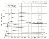
Graphical methods are useful to get the proper p-p load, But one of the best of these needs the plate family
where G2 is the variable, while G1 always at zero volts. I couldn't find that anywhere in either KT88 of 6550 data sheets,
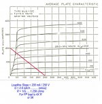
So to demonstrate the method I've used the plate family for the 6L6GC. This is accurate for Class A, less so for Class AB.
Start by drawing a loadline from the plate B+, then thru the knee of the G2 intended voltage.
For the PP 6L6 at 250V plate & screen the result obtained is 5K, just as published on the data sheet.
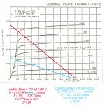
For the 6L6GC plate at 450V & the screen at 400V we see 4.8K Not quite the published spec, that is for Class AB.
Another loadline at plate 435V & screen at 200V looks like 12,5K.
That is a significant change caused by a different screen supply.
The best loadline can also be determined on a working circuit. But that assumes a usable CT OPT is available.
Easy to do, but another story.
Attachments
Thanks for the input. I've used the online loadline calculator from https://www.vtadiy.com/loadline-calculators/power-stage-calculator/ and I also used the classical pen and paper method by using the JJ KT88 datasheet.There were many suggestions regards OPTs. But everybody was way off as far as plate to plate load.
Looks like nobody thought about the very low screen voltage. That changes optimum p-p impedance;,
it goes up quite a bit.
Graphical methods are useful to get the proper p-p load, But one of the best of these needs the plate family
where G2 is the variable, while G1 always at zero volts. I couldn't find that anywhere in either KT88 of 6550 data sheets,
So to demonstrate the method I've used the plate family for the 6L6GC. This is accurate for Class A, less so for Class AB.
Start by drawing a loadline from the plate B+, then thru the knee of the G2 intended voltage.
For the PP 6L6 at 250V plate & screen the result obtained is 5K, just as published on the data sheet.
For the 6L6GC plate at 450V & the screen at 400V we see 4.8K Not quite the published spec, that is for Class AB.
Another loadline at plate 435V & screen at 200V looks like 12,5K.
That is a significant change caused by a different screen supply.
The best loadline can also be determined on a working circuit. But that assumes a usable CT OPT is available.
Easy to do, but another story.
Attachments
- Home
- Amplifiers
- Tubes / Valves
- KT88 amplifier