This is interesting for me, because I was looking at Hall-effect DC current transducers in order to directly measure anode current. It would be good to hear whether anybody has tried.I will post some pictures with the "final" product soon. Before I do that, I was thinking of adding a nice milliamp meter on the front panel so that I can see the bias current of the KT88s. I would also like to be able to switch between the four tubes. The thing is that I do not want to wire the cathode current through the windings of the analog ammeter. So this leaves me with the only option of measuring the voltage drop over the 3.3R cathode resistors. This means that will most probably need a V-I transconductance stage. This will convert the voltage drop over the cathode resistor (~190mV) into mA that will be displayed using the analog milliamp meter. I will also use a variable resistor in order to "calibrate" the whole thing. Are there any other solutions?
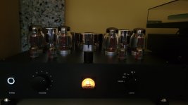
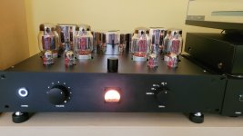
Yes, change the cathode resistors to 10R and use a mV meter where 50mA will read out as 0.5VI will post some pictures with the "final" product soon. Before I do that, I was thinking of adding a nice milliamp meter on the front panel so that I can see the bias current of the KT88s. I would also like to be able to switch between the four tubes. The thing is that I do not want to wire the cathode current through the windings of the analog ammeter. So this leaves me with the only option of measuring the voltage drop over the 3.3R cathode resistors. This means that will most probably need a V-I transconductance stage. This will convert the voltage drop over the cathode resistor (~190mV) into mA that will be displayed using the analog milliamp meter. I will also use a variable resistor in order to "calibrate" the whole thing. Are there any other solutions?

Yep that's simple or a 100mV meter. With the correct series resistor 3.3R cathode resistor can be left unchanged and 100mV = 100ma.
My approach would be to implement something like in the picture below:

R3 is the cathode resistor, R2 would be the milliamp meter and R5 would be adjustable. This circuit has a very low error on the scale I'm interested on. It will be supplied from one of the 6.3Vdc regulators that I use for the filaments of the input and driver stage. During normal operation I have around 190mV on the 3.3R resistors (~57mA) and the circuit will draw around 58mA from the 6.3Vdc supply. I will add a rotary switch before R4 and in this way I will be able to switch between all four tubes.
R3 is the cathode resistor, R2 would be the milliamp meter and R5 would be adjustable. This circuit has a very low error on the scale I'm interested on. It will be supplied from one of the 6.3Vdc regulators that I use for the filaments of the input and driver stage. During normal operation I have around 190mV on the 3.3R resistors (~57mA) and the circuit will draw around 58mA from the 6.3Vdc supply. I will add a rotary switch before R4 and in this way I will be able to switch between all four tubes.
AD8628 supply voltage should be 5V. Add small resistor from op-amp output to base of Q1. R1 is quite small do you need to make the voltage to the op-amp input so small ie is R5 needed?
The original 1mA d'arsonval analog meter movement DCR was 50 milliOhms.
That is full scale at 50mV.
Example 1mA meter setup:
1. A 3.3 Ohm resistor with 100mA current = 330mV
330mV - 50mV = 280mV
0.280V / 0.001A = 280 Ohms
Connect 280 Ohms in series with the 1mA meter; connect that across the 3.3 Ohms
That gives you 100mA full scale.
Note: with this setup, and a 5 way switch to select cathodes 1 - 4, and Off.
If the meter reads 1/2 way up the meter scale (50mA cathode current), you will add 0.5mA of cathode current to the one that is selected by the switch (50.5mA).
So a 5 way switch is best, it can have an off position.
Simple cathode current measurement: one 5-way switch, one 280 Ohm resistor, one 1mA meter.
Use the center switch position as the Off position.
Use the 2 left switch positions for the left channel cathodes.
Use the 2 right switch positions for the right channel cathodes.
"You should make things as simple as possible, but no simpler". Albert Einstein
Last edited:
I can also interrupt the shunt resistor (loop of wire) and use it as a voltmeter. I will then add a voltage divider with one of the resistors adjustable to be able to align the values.
After cutting the shut wire, the resistance of the meter itself is around 13R. By adding a ~73R resistor in series with the meter it should be ok. I will have full scale at 330mV over the 3.3R resistors. The only thing is that when the meter is connected, it will add 2.2mA of current through the tube I'm measuring (on top of the 57.6mA that goes through the tube). This will definitely create a small imbalance but I'm not sure whether this is something to worry about or not.
Nop but you could have an off position. It may create a click though in the speakers. If its a problem just add a unity gain buffer opamp.
Yes, I will use a buffer so that I will not disturb the current through the tubes. I will probably use a general purpose opamp like the tl072 or similar.Nop but you could have an off position. It may create a click though in the speakers. If its a problem just add a unity gain buffer opamp.
OK the KT88 cathode impedance Zo ~ 1/gm = 1/12*.001 = 83R. The cathode current is dominated by the KT 88 not by the 3R3. So the change of 100R across the 3R3 will have virtually no effect on the cathode current and therefore the operating point. So direct connection is fine - forget the op-amp. I am sure Mr Summer can explain this better. Clever solution to remove the shunt I was guessing you already had the meter. Also means the graticule is correct.
Last edited:
I think I understand what you are saying. The current through the tubes is not limited by the 3.3R resistors. Terese are just used so that we can measure the actual current that goes through the valves by using a simple voltmeter and not having to add an ammeter in series. So it does not matter weather these resistors are 3.3R or 1R or 10R. The current through the valves will be the same, just the voltage drop over the resistors will be different based on their value. You can even connect the cathodes directly to GND. This means that adding the meter will have no impact on bias current. I will make the modifications on Friday and I will post the results.OK the KT88 cathode impedance Zo ~ 1/gm = 1/12*.001 = 83R. The cathode current is dominated by the KT 88 not by the 3R3. So the change of 100R across the 3R3 will have virtually no effect on the cathode current and therefore the operating point. So direct connection is fine - forget the op-amp. I am sure Mr Summer can explain this better. Clever solution to remove the shunt I was guessing you already had the meter. Also means the graticule is correct.
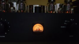
Indeed I already had the milliamp meter. It measures up to 100mA and I must say the precission of these milliamp meters is excelent. I tested one with a calibrated desktop multimeter and the readings were exactly the same. I was really surprised to see this 🙂
For 50ma adding a 100R across the 3R3 will change the voltage on the cathode by 5.3mV. This will change the current I = Vgm = 0.064ma. I think that's right? The shunt is probably trimmed to match the movement. I think as long as Rcathode << 1/gm this applies.
Last edited:
The core is gapped for that application, and that prevents DC from severely magnetizing the core to the point of saturation.Toroids can be used for SE applications as well as EI.
They are used since a long time with good results when compared to EI of the same "weight".
If you use a 1mA meter and low ohms series resistor, that combination is effectively a milli Voltmeter, so you can use the 5 way switch.
Simple works.
If you use a true 100mA meter in series with one cathode at a time to ground, that will work . . .
But do not use a 5 way switch, you have to use 4 meters. You can not switch a single current meter to 5 positions, unless it Also shorts the other 3
un-metered cathodes to ground.
And during any switching, if there is even a very brief moment of disconnect, one tube will be completely cut off . . .
Ouch! Potentially hurts your output transformer, loudspeaker woofer and tweeter, and your ears.
Not so simple.
You never told us that you already have a milliamp meter that should be used ...
Apart from that , to avoid breaking cathods and creating clicks in the speakers means that you measure voltage
across a cathode resistor with a voltmeter that has high enough resistance that it won't make detectable clicks.
( any meter with a preceeding opamp wil do and this will also give the possibility to calibrate the meter)
With this approach a 5 position switch is what you need, one position for each of the tubes and one position
where the meter is disconnected ( and protected).
I decided to use an opamp as a buffer before the 73R resistor and the meter. In this way I know for sure that the current going to the meter will not affect the current going through the tubes. I had a few AD8655s from another project and apart from the odd pinout, these should work like a charm. And indeed, these worked just fine. The only slight inconvenience was that AD8655 has a max supply voltage of 5.5V. But tat was ok as I had a few 5V LDO regulators laying around 🙂 (I know, I have many parts just laying around, maybe too many 🤦). I also added a rotary switch (non-shorting) on the input of the opamp and now I can see the current through all four tubes. I think that this concludes this project. At least for now 🙂.
Attachments


Hi, congratulations for your amplifier! I'm considering this build, may I ask if you can share the PCB design?Short update.
I went for the toroidal transformers in the end and I just ordered them from Toroidy.
2x Output transformers with the SUPREME option (encased in metal) : https://sklep.toroidy.pl/en_US/p/TTG-EL34PP-Tube-output-transformer-6,6kOhm-2xEL34-2x6L6-Push-pull-or-similar/562
1x power transformer with SUPREME option: https://sklep.toroidy.pl/en_US/p/TSTA-0220001-Mains-transformer-for-tubes/647
In the beginning I will do all sorts of teste but in the end i will put everything in an enclosure. I had very good interactions in the past with the guys form MODUSHOP so I will probably go for this enclosure: https://modushop.biz/site/index.php?route=product/product&path=118_251_252&product_id=120
PCBs are in progress at JLC PCB in China and I have most of the components ordered (TME and Mouser).
I can't wait to have everything and start building and testing 🙂
Hey @framilopes . I'm glad you want to try this amp as well. I've been using it for a while now and I'm really happy with it. As for PCBs, I can share the files with you but I'm not sure what format you want them. I can also sell to you the PCBs but first I have to check if I still have any. Otherwise I will have to order from China. You need three PCBs in total. One power supply and two power amps. Let me know how you want to proceed.
Hi @horias2000. Gerber files is ok, but it is your effort and hard work… I’m glad to buy from you or maybe as we have on our forum, a group buy. Please feel free to choose what is best for you. Thanks and congratulations for your build!
- Home
- Amplifiers
- Tubes / Valves
- KT88 amplifier