Updated drawing.
Whew - took awhile to get the upload file to size correctly. If you "click" on the file and "save" it you can view it as a gif file and zoom in pretty close for details.
Hope this helps. I'm still finding problems between the 50 Watt and 100 Watt schematics vs. the old pre-existing PWB and it's artwork. It's a work in progress - but - sigh - it's a labor of luv
Attachments

Samuel Jayaraj said:Steve, especially considering your situation, I just want to express my appreciation and gratitude for all your efforts thus far and all that you intend for the DIY community. With not even a finger, how do you manage to type so much? And that too with such prompt replies?
Hats off to you, Steve!!!
Much of my effort is my attempt at doing SOMETHING so I don't go insane. You can only watch so much TV.
Once it sank in that I would never work again I decided to make my work available to the public. I won't make money this way, but hopefully I will at least get credit for my designs. This site gives me the opportunity to pass on some of my knowledge and experience to those that are willing to accept it. That gives me some purpose in life at a time when I really need it.
As c2cthomas pointed out, I use voice recognition software to type. I don't mind answering questions or explaining why I have done something the way I have. Please don't let my condition stop anyone from asking.
Even before my miss fortune, Steven Hawking was a hero to me.
Some of us appreciate your effort and offer to share.
I personally am finishing up my shop / storage and will soon be starting my Krill so Thomas' drawing is coming at the perfect time.
I just finished "prototyping" the Mauro my Ref Rev_C on the kitchen table and don't want to do that again. That is what my shop / bench is for..
I personally am finishing up my shop / storage and will soon be starting my Krill so Thomas' drawing is coming at the perfect time.
I just finished "prototyping" the Mauro my Ref Rev_C on the kitchen table and don't want to do that again. That is what my shop / bench is for..
Attachments

Troy...... is this Mauro you told Mauro Pena from brasil?
Mauro Pena Societè Anonime (sociedade anônima.. S/A)....so.... SA...... Pena + SA... this results Penasa.
People thinks he is Italian...but i could see years ago his site in portuguese and the brazilian flag was there.
Maybe now more international...not more Pena....now Penasa....or there are other ones with the same name?
Is this one you are assembling?...one of his designs?
regards,
Carlos
http://www.webalice.it/mauro.penasa/
http://www.diyaudio.com/forums/showthread.php?s=&threadid=54571
http://www.diyaudio.com/forums/showthread.php?s=&threadid=133234&perpage=25&pagenumber=1
I don't know where he is from, but I built one of these and liked it. I had to "dispose" of it and then got a chance to build a second.
I hope to also build the 50W Krill and then give them to my kids with identical speakers. I will make them swap amps every 3-6 months so they can hear the difference.
This will teach them listening skills and put GOOD audio in their rooms...
In case you were wondering I am "in between" systems right now. I sold my JRDG Model 2 to build active bi-amp UcD based servo controlled speakers. I have all the parts, the speakers are built (SS Revelator tweets, B&W 805 6.5" mids, 2 x 10" PE Aluminum cone woofers per side) but the UcD modules and servo are still in the shipping boxes. I hope to build the cases that house the parts and serve as bases for the loudspeaker this spring.
troystg said:http://www.webalice.it/mauro.penasa/
http://www.diyaudio.com/forums/showthread.php?s=&threadid=54571
http://www.diyaudio.com/forums/showthread.php?s=&threadid=133234&perpage=25&pagenumber=1
I don't know where he is from, but I built one of these and liked it. I had to "dispose" of it and then got a chance to build a second.
I hope to also build the 50W Krill and then give them to my kids with identical speakers. I will make them swap amps every 3-6 months so they can hear the difference.
This will teach them listening skills and put GOOD audio in their rooms...
Ya got a spare room that I can move into?

ehhehehehe Thomas is funny.
Thank you by the links Troy....now i am understanding.... my own confusion....he is from Italy and not the same one i have visited into a Brazilian home page
It's all rigth.
Carlos
Thank you by the links Troy....now i am understanding.... my own confusion....he is from Italy and not the same one i have visited into a Brazilian home page
It's all rigth.
Carlos


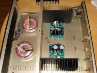
Received my boards today.
Will post my observations as soon as I begin building the amp.
Ciao
Andrea
Will post my observations as soon as I begin building the amp.
Ciao
Andrea
I spent a little time over the weekend redesigning the 50W amp to make it more affordable. Switching to the Fairchild transistors and cutting back on the power supply filter caps cut a fair amount of money from the BOM. If you use this to build a stereo amp and use only one transformer and case you can save even more. For surround sound, you can put even more channels in one case with one transformer.
Much of the reason for giving you this option is the use of multi channel surround sound. You really don't need over 50W and building an all out amp can be expensive. Another reason is some of you would prefer to spend less money.
If there is sufficient interest, I will put together full kits with transformers as an option. There are no circuit boards for this amp at this time. That would need to be laid out and priced. The boards I still have will work but I would need to renumber parts on the schematic and BOM to match. Also, I can not guarantee the lead spacing for the caps will be correct. At this time I would not offer cases or heat sinks.
All parts are available from DigiKey and Mouser. I have made a BOM in Excel that lists all part numbers used as well as their schematic designations. If you can't order from these suppliers for any reason, you can still check the data sheets for the parts on their web sites. This will give you the lead spacing and sizes of all the components if you make your own boards.
I have attached the new schematic.
Attachments
I am just a lurker here, having to many projects, that needs to be done.
But i have to say "Kudos to You" Steve, for Your hard work sharing this with all of us.
This i a project i will definitely have to try out, when i get the the table cleared of half-finished stuff 😀
A BIG thank You from me.
Best regards
Ebbe
But i have to say "Kudos to You" Steve, for Your hard work sharing this with all of us.
This i a project i will definitely have to try out, when i get the the table cleared of half-finished stuff 😀
A BIG thank You from me.
Best regards
Ebbe
Steve Dunlap said:No opinions on the servo yet? Once we discuss that I will move on to improvements in the power supply. Remember, this design started over 25 years ago. I have made improvements through the years, but these do not make the original design invalid. Many people still listen to the original amps and are very satisfied still when comparing them to new high end gear.
Hi Steve, nobody has given an opinion on your DC Servo, so I will ask a couple of questions ...
Can this servo be used for the 50 & 100watt Krill versions?
Does the servo improve the performance of the 50, 100, & 200watt Krill versions?
🙂
Hi Steve,
You mentioned that the DC Servo will handle a small DC voltage and correct it, is it possible to the servo then activate an external protection circuit.
Cheers
Rob
You mentioned that the DC Servo will handle a small DC voltage and correct it, is it possible to the servo then activate an external protection circuit.
Cheers
Rob
Rob_S said:Hi Steve,
You mentioned that the DC Servo will handle a small DC voltage and correct it, is it possible to the servo then activate an external protection circuit.
Cheers
Rob
I will answer Rob_S question first. Yes. The servo can null out a small DC input from a source that has one. The limit of this will be about 1 volt plus or minus. This would indicate a defective source. This will compromise the performance of the amp to some degree. Still, this is better than having an amp output of up to 25 or 30V DC. To incorporate a true protection circuit I would use two dual op amps. One half of of each would adjust the servo and the other half would activate the protection. The op amp for the VGA would also be used to mute the input to the amp. There is more than one way to do this. This would remove the DC input and should be set to activate faster than the output protect to prevent possible damage to the amp if using a crowbar type circuit. Just as with the input mute, there is more than one way to shut off the amp output.
KLe said:
Hi Steve, nobody has given an opinion on your DC Servo, so I will ask a couple of questions ...
Can this servo be used for the 50 & 100watt Krill versions?
Does the servo improve the performance of the 50, 100, & 200watt Krill versions?
🙂
The servo shown can be incorporated into any of my amps. You will need some extra board space for the added components.
I realise I left the power supply for the op amp of the schematic. I assume anyone undertaking a project of this nature could Handel a 15V bipolar supply.
The servo does not improve the performance over trim pots used in the same locations. It does do the adjustments for you. Results are similar either way.
You asked about the slow response time of the LDR. The one I use has a response time of 5mS with final adjustment under 10mS. The circuit does not use this response time to make it operate properly.
Referring to the 200W amp schematic, R14 is set high so the VGA will start with a small +DC voltage at its output. This is amplified by U1b and applied to the LED in the LDR. The LDR decreases in resistance until the DC voltage is no longer high enough to keep the LED from drawing more current and the parallel resistance of R14 and the LDR have reached the proper value. R45 prevents the range of adjustment from going too far outside operating parameters if the LDR should somehow become shorted.
The output servo does pretty much the same thing except that the voltage it amplifies can be of either polarity. This voltage is applied to the base junction of Q17 and Q18 turning on the transistor that needs to be on to drive the proper LDR. When the DC becomes low enough the LDR stabilizes and keeps it low. Q30 and Q31 insure that everything will continue to work safely if the LDR or the op amp fails.
Steve, are the 78xx and 79xx regs good enough for the DC Servo? Is there any more information we should know about re. the DC Servo ... 🙂
KLe said:Steve, are the 78xx and 79xx regs good enough for the DC Servo? Is there any more information we should know about re. the DC Servo ... 🙂
Those regs are good enough. I would just use resistors and zeners. The power supply for the op amp is of no great importance as long as the voltage is acceptable and there is enough current. The op amp will need enough current to output 20mA from either or both halves.
The op amp is only driving the LED in the LDR. The LDR acts just like a trim pot only it stops automatically at the correct resistance. There will be some trade off in servo speed if C31 and C32 are made larger, but it will result in a slightly more stable output voltage from the op amp. Since the LDR is parallel with a low value resistor, any changes in its value results in a very small net change.
- Status
- Not open for further replies.
- Home
- Amplifiers
- Solid State
- Krill - The little amp that might...