Solid state would make some sense, however anyone with a project that is not a speaker will still need a metal case.
I checked with an on line metals source since my last post. I used the dimensions of my current preamp (17" x 9" x 3" with a 3.5" x 19" faceplate) because I would like to replace it. The price for pre cut to size Al with shipping was $85. This was using .09" plate for top, bottom, front and back with .25" side panels and faceplate. You can save money by using thinner metal, but I would not recommend thinner than .0625 for larger flat pieces. This is thick enough to mount heavy objects like transformers. Does this seem to be a reasonable price for a nice case? Some assembly required.
I am not selling these. I only plan to give some sources for on line metals and directions (with pictures) of how to build your own. Think of it as a DIY thing.
http://www.onlinemetals.com/
Check for sources near you or that will ship to you.
Hi Steve - I looked around and couldn't find anything that would be nearly as nice as the chassis you are describing! 😎
OH MAN - now I will need to decide on the titanium or the carbon fiber! Ohh - and brass and copper too!!
Add a touch of wood and maybe an LED or two and - WOW! 😀 😀 😀
I've been considering something to slap about 4 of your monoblock amps into (one per chassis - for bi-amp project) along with some type of built in active crossover that could be user adjusted (freq. and slope). Still considering the use of (dirty word) opamps or xsistors for that little guy tho -.
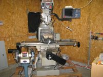
As long as I don't need to come over and use your mill to machine something out of solid stock - I'm game!
OH MAN - now I will need to decide on the titanium or the carbon fiber!
Ohh - and brass and copper too!! Add a touch of wood and maybe an LED or two and - WOW! 😀 😀 😀
I've been considering something to slap about 4 of your monoblock amps into (one per chassis - for bi-amp project) along with some type of built in active crossover that could be user adjusted (freq. and slope). Still considering the use of (dirty word) opamps or xsistors for that little guy tho -.
As long as I don't need to come over and use your mill to machine something out of solid stock - I'm game!
Attachments
Thomas-
Marchands XM-1 works well and is inexpensive.
I have a couple of these if you need some:
http://www.diyaudio.com/forums/showthread.php?s=&threadid=74420&perpage=25&pagenumber=1
Marchands XM-1 works well and is inexpensive.
I have a couple of these if you need some:
http://www.diyaudio.com/forums/showthread.php?s=&threadid=74420&perpage=25&pagenumber=1
troystg said:Thomas-
Marchands XM-1 works well and is inexpensive.
I have a couple of these if you need some:
http://www.diyaudio.com/forums/showthread.php?s=&threadid=74420&perpage=25&pagenumber=1
Hi Troy - Thank You for the offer - I might take you up on it - but I would want to compensate you for the cost. I'm thinking of something very similar - but I'm thinking of adding a header (like the ones used on hard disk drives that select "master" or "slave") to select the values of the resistors and caps and thus let me muck around a bit more than soldering components into and out of circuit and then guess if I'm hearing something better or not. I haven't read the Bob Ellis thread so I think I'll give that a look and see what he came up with there (sharp guy). I for sure want to build the circuit into the amp tho-
I have checked out the Marchand stuff before and was very interested in his OEM line of amps for doing self powered speakers. All things are under consideration pending surplus $$$$.

c2cthomas said:I've been considering something to slap about 4 of your monoblock amps into (one per chassis - for bi-amp project) along with some type of built in active crossover that could be user adjusted (freq. and slope). Still considering the use of (dirty word) opamps or xsistors for that little guy tho -.
In case I have two boards for the Delta Audio Active filter two that does exactly what you need.
info here : http://delta-audio.com/Active filter two.htm
These are almost completely stuffed (just some Q- setting resistors missing). I'd gladly trade them for a pair of Krill boards.
Ciao
Andrea
Andypairo said:
In case I have two boards for the Delta Audio Active filter two that does exactly what you need.
Ciao
Andrea
Ciao Andrea,
Milano! A beautiful place to be living life! During my Navy days I was able to see Venice and Naples several times and fell in love with northern Italy. I was reading about this circuit board last night and regretting that the group buys have gone bye-bye and now they are difficult to obtain unless I would want to make some myself. To many holes to drill to be thinking about doing such a thing! Also - they use a potentiometer in the circuit which I don't like - but I would just put in a fixed value there after determining what I needed. I don't know what Steve's Krill boards cost - but I can inquire. Would you be wanting the boards stuffed or just bare? Also - the boards that Steve has at the moment are for the monoblock amplifier - not the stereo boards that have been discussed in this thread earlier.
Thomas
Steve, I set out to design a PCB for your amp in post #21, wherein upto the driver stage the rail voltage is run higher. I also thought of doubling the output devices to be able to feed them off transformers I readily have which will have higher voltages.
I ran into a problem wondering which devices mount on the output heatsink and if D5-D7 are also in thermal contact with the heatsink?
A clarification will be much appreciated. Thanks.
I ran into a problem wondering which devices mount on the output heatsink and if D5-D7 are also in thermal contact with the heatsink?
A clarification will be much appreciated. Thanks.
Hi Sam,
E-mail me and I will send you a Zip file with more info.
Doubling the output devices will allow operation up to 100W at 8 ohms and 200W at 4 ohms. Four pair will allow operation to 200W and 400W respectively. For outputs over 50W at 8 ohm I recommend using the same transistors for drivers as used for outputs. This insures greater reliability especially at lower impedances. All of this depends on proper heat sinking of course.
If your supply voltages go over +/- 50V a small heat sink on each of the TO220 transistors will also improve long term reliability.
The drivers and output transistors all go on the heat sink. Diodes 5,6 and 7 are mounted to the heat sink (near the center) for thermal tracking. The art work for this diode board is also included in the Zip file.
Be sure to check the schematic in the Zip file as any errors that I made in earlier posts have been corrected (I hope). The schematic designations are different for many components because I drew it to match the boards I still had in stock.
If you have more questions, please ask them here, not in E-mail, so it will benefit all interested parties.
I have redrawn my 50W amp schematic to correct some minor errors and to incorporate the newer part numbers. If anyone would like the new Zip file which includes the schematic, board top and bottom art, stuffing guide, diode board and drawing of the heat sink I used when the 100W amp was manufactured. The heat sink lines up with the outputs and drivers. This gives you the hole spacing to make your own heat sink. E-mail if you would like to receive the Zip file. It is too large to post here.
I have attached the new schematic.
I have attached the new schematic.
Attachments
Since you ask, I have made a price list for full kits (no cases) and partial kits. If you are interested E-mail me.
Hi Steve,
Is it really OK to bypass the transformer like that in your PSU?
People need to be very careful in 240V countries. Most of our transformers only have a single primary.
regards
Is it really OK to bypass the transformer like that in your PSU?
People need to be very careful in 240V countries. Most of our transformers only have a single primary.
regards
Greg Erskine said:Hi Steve,
Is it really OK to bypass the transformer like that in your PSU?
People need to be very careful in 240V countries. Most of our transformers only have a single primary.
regards
I'm not sure I understand what you mean by bypass. What I am showing is a transformer with dual primaries for use at either 120V or 240V. I have them shown in parallel for 120V. They would be wired in series for 240V. I have certainly made my share of mistakes. If there is a problem with the way I have drawn this please bring it to my attention.
I assumed that each person would know what their local voltage was and purchase their transformer accordingly. The transformers with my kit have only one primary rated for 120V 50/60 Hz. Anyone considering these should be aware of that. The only way to use them on 240V would be to wire the primaries in series. This could present a problem in mono block amps, but is very simple if both transformers are in the same enclosure.
Steve Dunlap said:I'm not sure I understand what you mean by bypass. What I am showing is a transformer with dual primaries for use at either 120V or 240V. I have them shown in parallel for 120V. They would be wired in series for 240V. I have certainly made my share of mistakes. If there is a problem with the way I have drawn this please bring it to my attention.
I don't pretend to be speaking for Greg, but I'll give you my take on things. Looks as if R21, D17, C15 and R22, D20, C16 are wired to the primary side of the xformer. In some places that would be a big no-no because the xformer is no longer providing isolation from the input AC.
For the people that have purchased boards (thank you) I need to point out that the capacitor on the board in the ground of the VGA feedback loop is not shown in the schematic. This is C22 on the board and stuffing guide. If you use the trim pot (R60) I show in the schematic then C22 is replaced with a jumper. I think I mentioned this before but I don't want anyone to encounter problems because of this. Leaving out the jumper will set the VGA at unity gain.
I will post a schematic WITH C22 and without the trim pot for those that prefer not to use the trim method for DC offset adjustment. The value of the resistor parallel with the trim pot (R12) will be different. No other changes would be needed.
I will post a schematic WITH C22 and without the trim pot for those that prefer not to use the trim method for DC offset adjustment. The value of the resistor parallel with the trim pot (R12) will be different. No other changes would be needed.
I have attached the new schematic.
VERY nice schema , now I can read it better.. Added it to
the collection.😎
I might make a board for it..
OS
Like I said, I have made my share of mistakes. You are correct and I have shown this incorrectly. The resistors (R21,R22) should connect to the secondary side NOT the primary. I will change this on the schematic and re post.
Thank you Greg and and c2cthomas for pointing this out. If anyone sees any other problems or just have questions about why I did something the way I did, please ask.
Thank you Greg and and c2cthomas for pointing this out. If anyone sees any other problems or just have questions about why I did something the way I did, please ask.
ostripper said:
VERY nice schema , now I can read it better.. Added it to
the collection.😎
I might make a board for it..
OS
Thanks ostripper. Now you can update with the corrected schematic as soon as I post it. Keep us posted on the board if you do it and of course I know you will make it available to the DIY community.
Any of you young guys that think you have made a big mistake, don't get too cocky. I made those mistakes long ago and I'm still at the top of my game. You will be playing catch up the rest of your lives.
Yes , even we young ones screw up.. Andrew T. found myBy steve - Like I said, I have made my share of mistakes. You are correct and I have shown this incorrectly
schematic mistakes this morning even after I triple checked
them.
Luckily the PCB was perfect..so no fried newbies 😀
My krill ??question is why did you design with such low
rail voltage/wattage. the young ones crave POWER...
or they just bounce off to the class D threads to get their
1/2 KW. When I do the krill , 60 volt rails will be the fact,
because 40-0-40 volt trafo's are so common (trashed
HT receivers).
OS
c2cthomas said:
I don't pretend to be speaking for Greg, but I'll give you my take on things. Looks as if R21, D17, C15 and R22, D20, C16 are wired to the primary side of the xformer. In some places that would be a big no-no because the xformer is no longer providing isolation from the input AC.
If I see the components correctly he is using a dropping resistor (R21 / 22) and then half wave rectifying (with soft switch bypass cap) the reduced AC..
What is the difference between that and the BR directly on the mains input like in SMPS?
Yes those components are "high voltage" components, should be on the PS PCB / section and treated accordingly, but to my knowledge there is nothing controversial there.
- Status
- Not open for further replies.
- Home
- Amplifiers
- Solid State
- Krill - The little amp that might...