roender said:
Not entirely true. Yes, the total amount of distortions will increase with the current, after the optimal Iq point, but the high order harmonics will decrease actually.
Are you referring to a real or simulated amp? Is it my output stage?
Steve Dunlap said:
Are you referring to a real or simulated amp? Is it my output stage?
I am refering to this amp
http://www.diyaudio.com/forums/attachment.php?s=&postid=1349109&stamp=1194852081
from this diyaudio thread
http://www.diyaudio.com/forums/showthread.php?threadid=111756
but I think it is not dependent of topology if that is class B as per Douglas Self definition
Steve, your output stage is very interesting and original. It will be a pleasure for me to construct a version based on ONsemi ThermalTrack transistors (at least 6 pcs)
Carlos:
Attached in the next few posts are the old boards I still have in stock. They are the same as the ones c2cthomas (Tom) sent you. They were for a 100W mono amp using 2 pair of outputs. For 50W you may leave out the second set. I have also included a stuffing guide that (hopefully) matches the board and schematic.
I just got a message the file is too large. I will Zip them and send them to your E-mail.
Carlos wears a new hat
Ah, this is a nice turn. Carlos reaches into his closet and goes beyond the shotgun and pulls out the hat of a diplomat (diplomata).
Very good, Carlos.
Have a Wonderful Merry Christmas 😀
Ah, this is a nice turn. Carlos reaches into his closet and goes beyond the shotgun and pulls out the hat of a diplomat (diplomata).
Very good, Carlos.
Have a Wonderful Merry Christmas 😀
Yes.... trying to be Diplomata.... this is needed sometimes
Shotgun is taking a good rest...but i am missing it as a hell.
I would like to give some shots.... with salt in place of lead pellets...some folks deserves a salt shot directly into the hear sitting bumper.
Booom!
ahahahah!
Merry Christmas dear Mongo....not only to you but to all good forum folks.
The bad guys...well..for them a shot of salt...buuuuummmm!... in english is "booom"..but has double meaning..engage brain folks.
Carlos
I do love simulations too... but i do not trust them entirelly
In my imagination my ears, your ears, our ears, human ears are better instrument...because at the end, they will be the tool we gonna use to listen.
In the reality is ears plus brain plus conscience.
Not a very simple thing as mathematics calculations.
regards,
Carlos
In my imagination my ears, your ears, our ears, human ears are better instrument...because at the end, they will be the tool we gonna use to listen.
In the reality is ears plus brain plus conscience.
Not a very simple thing as mathematics calculations.
regards,
Carlos
Attachments
troystg said:It looks as though Steve already HAS PCB's for his amp..
http://www.diyaudio.com/forums/attachment.php?s=&postid=1685764&stamp=1229341482
Would you be interested in a GB of those? Obviously they are already tested and working.
troystg said:
When I made the above statement I should have been more clear.
I was asking Mr. Dunlap if he wanted to use his already designed PCB's or if he would like to do another one.
I'm not sure I ever addressed this issue properly. I do have about 100 of the boards shown in Tom's pictures. These are the one in the small mono amp and shown in another picture un-stuffed. The amp was 100W at 8 ohms and used two pair of outputs. This board will work for a 50W amp. You could either leave out one pair of outputs or use two pair of a lower power rating. You could also use both pair for a more rugged amp at low impedances, such as 2 ohm.
These boards differ slightly from what I have posted in this thread. The changes are minor and consist primarily of differences in part numbering in the schematic. I have the schematic that matches this board along with a stuffing guide that I will send anyone interested if they E-mail me directly.
I will continue to work (slowly) on a board layout for the schematic I posted as well as an output only board for those interested in using a different VGA.
Feel free to inquire about other parts such as transformers, filter caps or heat sinks that you might find useful for this project or some other project you have in mind.
Steve
Absolutely!
I was offering to to do the labor of having PCB's manufactured, funds received, and boards shipped out to builders.
Buuuttttt.... If you have boards already made I would be happy to buy a set!
The offer still stands to get the boards from you and ship them out to all the people who buy a pair... I have the old affliction of a strong back and weak mind... I can do the labor for you to save you the pain...
Thanks troystg,
Send me an E-mail and we can talk this over. IF my e-mail is working. I havent even recieved spam since early yesterday.
Steve
Send me an E-mail and we can talk this over. IF my e-mail is working. I havent even recieved spam since early yesterday.
Steve
I guess I should mention that on the surplus boards I have there are pads for two pair of outputs. This is because they were used in 100W amps. At 50W, the second pair does not need to be used, but may be if desired. Also, on these boards the driver transistor used was the same as the output transistors. This will make mounting a TO220 transistor a little less straightforward. The pin outs are the same, but the size is different. If you decide to use these amps as higher power at 8 ohms or to run impedances below 4 ohm I would recommend using the same transistors for output and driver pairs.
I would be very happy to get at least 2 boards once prices and shipping options have been decided (assuming we are moving in that direction).
Thank you for your willingness to share your circuit!
Steve.
Thank you for your willingness to share your circuit!
Steve.
Steve,
I'm watching this with great interest. I know if Troy is allowed to assist, he'll do a fine job, as he has in the past.
The 100 W version has my attention...
I'm watching this with great interest. I know if Troy is allowed to assist, he'll do a fine job, as he has in the past.
The 100 W version has my attention...
Those of you interested in boards should E-mail directly. I have a Zip file with both sides of the board, stuffing guide and schematic that matches the board. It is slightly different from what is posted on this thread. The difference is mainly schematic component numbers. I have also included a drawing of the heat sink I used on the 100W amp. This should help with hole placement when you drill your own heat sink. The Zip file is too large to post here.
Steve
Steve
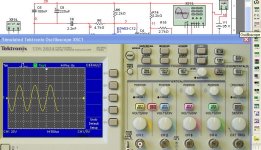
It (the krill) simulated perfectly.. first time!! what a blindingly fast amp with a strange topology.
It seems to "self bias" at 50-60ma OP wise and its offset
is determined by LTP current.
With no passive compensation (Cdom), it is only comp'ed
by device Cob.. next post
I ran it with modern devices and it will do a perfect 100k
squarewave with a little overshoot (the faster fairchild
devices)..
It seems to "self bias" at 50-60ma OP wise and its offset
is determined by LTP current.
With no passive compensation (Cdom), it is only comp'ed
by device Cob.. next post
I ran it with modern devices and it will do a perfect 100k
squarewave with a little overshoot (the faster fairchild
devices)..
Attachments

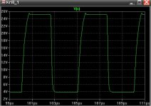
Here is that little overshoot I noticed (no doubt the KSA devices)
The 2 problems with doing a proper test on this amp is its
lack of global NFB (how to loop my AC analysis) and how
would I comp. for faster devices?? Still i would estimate
80-120 V/uS for this amp..
The 2 problems with doing a proper test on this amp is its
lack of global NFB (how to loop my AC analysis) and how
would I comp. for faster devices?? Still i would estimate
80-120 V/uS for this amp..
Attachments
ostripper,
Thanks for the input and confirmation of my amp. In the schematic you posted you have C7 between the bases of the output pair (you probably looked at one of my posts where I had it wrong). C7 goes between the bases of the driver pair, C14 and C15 in your schematic. The value in your schematic also looks to be 47uF. It should be from 1uF up to 4.7uF.
Once again, thank you for your time and input.
Steve
- Status
- Not open for further replies.
- Home
- Amplifiers
- Solid State
- Krill - The little amp that might...