We might be able to use those here too:
http://www.diyaudio.com/forums/showthread.php?s=&threadid=133234&perpage=25&pagenumber=1
Read the last few posts... Page 9 and 10...
http://www.diyaudio.com/forums/showthread.php?s=&threadid=133234&perpage=25&pagenumber=1
Read the last few posts... Page 9 and 10...
megajocke said:
Good to hear you are getting better 🙂
I posted a simulation of transconductance a while back, could you have a look at it? Now, with real parts the problem will probably not show up on many amplifiers as it needs pretty good matching between PNP:s and NPN:s. If there is enough mismatch (and there will probably often be) the deadband will be outside the normal output currents the amplifier is asked to deliver.
Do you use feedback around the whole amp or is it always just around the front end?
The intention of this when I designed it was to produce a sonically acceptable amp that could be built and sold very cheaply. Off the shelf parts without matching helps to achieve that goal. You may have noticed also that all resistor values (except trim pots) are in the 5% column. More precise may be used, but once again the less expensive option was made available. With the ready availability of 1% resistors these days along with their reduction in price it would make sense to use them.
I would be reluctant to comment on your simulation of the trans conductance. I have found this circuit to be very difficult to accurately simulate and what you get in the simulation, even when it looks good, may not match what is happening in the real amp. As an example: It was suggested that the C to E could be shorted together on one of the bias transistors or replaced with a diode. I didn't try the diode, but when you simulate the circuit with the C E short it works fine in the simulation. If you do this to a real amp you will remove the base currents to the bias pair. The shorted one won't care (because it is now out of the circuit) but the opposite in the pair will turn off. This allows 10mA of current from the current source to place nearly the full rail voltage on the corresponding driver base. As a result, the output turns fully on. Not good.
Steve
While I was mailing Carlos his little package of parts this guy and his very attractive GF were standing in front of me in line. It's nice to see a local boy do good! 😀
BTW - booth were very nice and polite. Not stuck on themselves or have any attitude about being better than those around them. It was a long line and they waited for their turn just like everyone else. Brad talked to people that wanted to say something. Nice Guy!! 😉
Driving a Nissan Altima - they make those cars here in town.
Attachments

troystg said:"I have no problem with anyone making boards for their own use. I do not feel it would be fair to produce the boards in quantity for sale."
Mr. Dunlap-
My ONLY goal here is to make what ever design you decide to share with this community available to to this community. It is done as volunteer work in good intentions. I have no desire nor need to profit from someone else's work.
If you have any doubts please review the GB I did for the Krell KSA-50 clone thread. I ran a GB for PCB's and parts.
I enjoy building things when I have time / chance but unfortunately I am not an Engineer able to create them. So I do my best to enable myself and others to be able to build what the true talent (too many to list, and I would be afraid to leave someone out) on this forum offer to us.
"IF" I were to do a GB it would be WITH your permission and blessing, on a PCB that the GROUP decided was ready and it would be AT COST. I would suggest a donation to DIY Audio and to you for sharing the design but again that would be at the group and your discretion.
This is acceptable to me. I simply wanted to make my feelings clear about someone trying to market my design without my permission or knowledge for their personal gain. We all know this happens. Just ask Nelson Pass.
I have taken no offense at your offer.
Steve
Steve Dunlap said:
It was suggested that the C to E could be shorted together on one of the bias transistors or replaced with a diode. I didn't try the diode, but when you simulate the circuit with the C E short it works fine in the simulation. If you do this to a real amp you will remove the base currents to the bias pair. The shorted one won't care (because it is now out of the circuit) but the opposite in the pair will turn off. This allows 10mA of current from the current source to place nearly the full rail voltage on the corresponding driver base. As a result, the output turns fully on. Not good.
Steve
Why would shorting C-E on one of the transistors remove its base current? Think of how a transistor is built. Zero collector current doesn't cause zero base current. Zero base current usually causes zero collector current though (if there is collector-emitter voltage available). Actually, removing collector current will increase base current for the same B-E voltage!
Taking an NPN and shorting its collector and emitter together essentially creates a diode but with only ~7V reverse breakdown due to the way the E-B junction is done. The base will become anode and collector/emitter cathode. You can also do it with one of the collector or emitter pins floating or conneted to the base. (like in a current mirror, the transistor is used as a diode there). Polarities are opposite for PNP:s of course!
c2cthomas said:While I was mailing Carlos his little package of parts this guy and his very attractive GF were standing in front of me in line. It's nice to see a local boy do good! 😀
BTW - booth were very nice and polite. Not stuck on themselves or have any attitude about being better than those around them. It was a long line and they waited for their turn just like everyone else. Brad talked to people that wanted to say something. Nice Guy!! 😉
Driving a Nissan Altima - they make those cars here in town.
That is his wife. Or maybe girlfriend. You never know with celebrities. I guess they were sending presents and cards back home to Australia.
Funny thing about this town. You can't throw a rock without hitting someone famous. And you can't throw a stone without half the city showing up! 😀
megajocke said:
Why would shorting C-E on one of the transistors remove its base current? Think of how a transistor is built. Zero collector current doesn't cause zero base current. Zero base current usually causes zero collector current though (if there is collector-emitter voltage available). Actually, removing collector current will increase base current for the same B-E voltage!
Taking an NPN and shorting its collector and emitter together essentially creates a diode but with only ~7V reverse breakdown due to the way the E-B junction is done. The base will become anode and collector/emitter cathode. You can also do it with one of the collector or emitter pins floating or connected to the base. (like in a current mirror, the transistor is used as a diode there). Polarities are opposite for PNP:s of course!
Second paragraph first. Shorting the collector to the emitter takes the transistor out of the circuit. Shorting the collector to the base makes a diode. If there is no current flowing in the emitter then there is no current flowing in the base. When you short C to E no current will flow in any pin. Emitter current = collector current + base current. C = E (because they are shorted together) therefore B = 0.
Steve Dunlap said:
That is his wife. Or maybe girlfriend. You never know with celebrities. I guess they were sending presents and cards back home to Australia.
Funny thing about this town. You can't throw a rock without hitting someone famous. And you can't throw a stone without half the city showing up! 😀
Steve - get a grip dude! That's Brad Arnold - lead singer for 3 Doors Down. Happens to be a band I listen to often (on the stereo - not live). The Aussies live over in Brentwood.
Hmmm - Manfred the Wonder Dog had his back surgery done over there and I get to bring him home tomorrow. Who knows - maybe I'll run into 'em over at the vet's.

Attachments

I guess I should have looked closer at the drum. It has the band name on it. I really couldn't really make the singer in the picture. I was thinking Braid Paisley and Nicole Kidman. Also locals.
Ah you rockers - I thought you were talking about Brad Pitt but then I have never heard of 3 doors down until I read it off the drums in the pic. - are they any good?
Glad to see the pcb issue is clarified!
DX, Carlos, any chance you might host a sound clip from the amp on Youtube as per your DX amps? I believe this would spread the word.
When you initially, hosted these sound recordings on youtube I thought what's the point the sound is not good enough to tell how good an amp is but I came to realise that I can compare & hear the difference between your amps
Thomas, you have mail (in a minute)!
Originally posted by Steve Dunlap
Second paragraph first. Shorting the collector to the emitter takes the transistor out of the circuit.
No way 😀 Try taking an NPN transistor, collector conneted to nothing. Put red lead of multimeter in diode test mode on base pin, black lead on emitter. Current will flow, and the voltage drop will be 400-700mV depending on transistor size, current and temperature. Same will happen with black lead on collector. But if you were right no current would be able to flow in this case. Look at this simplified picture of internal structure for an explanation:
http://fourier.eng.hmc.edu/e84/lectures/figures/transistorBJT1.gif
Connecting CE together to black lead and red lead on base will of course also give a reading of around 400-700mV!
An NPN BJT is like two diodes connected with anodes to the base with the peculiar property that forward biasing one of the diodes makes it possible for current to flow from collector to emitter or vice versa. Reverse all polarities for a PNP.
Originally posted by Steve Dunlap
Shorting the collector to the base makes a diode.
Yup, and a very useful one too when matching to another transistor is needed!
Originally posted by Steve Dunlap
If there is no current flowing in the emitter then there is no current flowing in the base.
Only true if no current is flowing in the collector.
Originally posted by Steve Dunlap
When you short C to E no current will flow in any pin.
Not if you forward bias the BE and BC junctions by making the base positive in regards to C and E for an NPN.
Originally posted by Steve Dunlap
Emitter current = collector current + base current.
But now you defined the emitter current in the other direction compared to base and collector current. (emitter current coming out while base and collector are going in or vice versa). This is Kirchoffs Current Law: Ie + Ib + Ic = 0 if all currents are defined in the same direction.
Originally posted by Steve Dunlap
C = E (because they are shorted together)
Would be true if collector and emitter junctions were identical, but doesn't matter.
Originally posted by Steve Dunlap
therefore B = 0.
No, base current going in equals the sum of current coming out of collector and emitter. If IC = IE then this means (-Ib) = Ie+Ic = 2Ic = 2Ie.
megajocke said:
No way 😀 Try taking an NPN transistor, collector conneted to nothing. Put red lead of multimeter in diode test mode on base pin, black lead on emitter. Current will flow, and the voltage drop will be 400-700mV depending on transistor size, current and temperature. Same will happen with black lead on collector. But if you were right no current would be able to flow in this case. Look at this simplified picture of internal structure for an explanation:
http://fourier.eng.hmc.edu/e84/lectures/figures/transistorBJT1.gif
Connecting CE together to black lead and red lead on base will of course also give a reading of around 400-700mV!
An NPN BJT is like two diodes connected with anodes to the base with the peculiar property that forward biasing one of the diodes makes it possible for current to flow from collector to emitter or vice versa. Reverse all polarities for a PNP.
Yup, and a very useful one too when matching to another transistor is needed!
Only true if no current is flowing in the collector.
Not if you forward bias the BE and BC junctions by making the base positive in regards to C and E for an NPN.
But now you defined the emitter current in the other direction compared to base and collector current. (emitter current coming out while base and collector are going in or vice versa). This is Kirchoffs Current Law: Ie + Ib + Ic = 0 if all currents are defined in the same direction.
Would be true if collector and emitter junctions were identical, but doesn't matter.
No, base current going in equals the sum of current coming out of collector and emitter. If IC = IE then this means (-Ib) = Ie+Ic = 2Ic = 2Ie.
You are right. I am an idiot. I just assumed we were talking about transistors in a circuit. This one specifically. If you simply take the transistors OUT of the circuit, it works just as you say. Almost.
Oh!.... i have moved to the third room, now i have a separated
room only to electronics... almost outside home... confortable....
But here sound behaves very different... to produce recordings to compare to old ones will be a hell...but i will try to find a way to switch and them compare Dunlap amplifier with my Dx Standard for instance (sounds very different one compared to the other...better to Dunlap in trebles and better to Dx Standard to basses... my taste if for stronger loosen, non perfect basses)
Well...tomorrow i will think to produce..if neighboors not to produce too much noise around... and they are producing a lot of noise because children are on vacations from school.
regards,
Carlos
..........................................................................................
I am not answering or commenting all messages to me because thread was opened by Steve... and he is the one to answer things..but i ensure you all that i am reading each letter, each line, from ALL of you.
Carlos
Steve Dunlap said:
You are right. I am an idiot. I just assumed we were talking about transistors in a circuit. This one specifically. If you simply take the transistors OUT of the circuit, it works just as you say. Almost.
But the transistors will not magically start to work another way when put into the circuit so it won't blow up like you say. But maybe you misunderstood what I meant by shorting them together (those two wires coming out at the bottom are the ones I mean in my diagram). This makes Q5 a diode just like the others in the string and it will work just fine. Q8 will drive Q4 directly and Q6 will provide bias voltage for the output stage, without undefined or very nonlinear behaviour. But that doesn't really matter for the problem and in the following text, is not done.
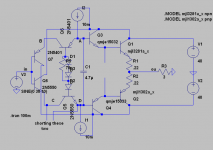
The problem I'm talking about is something that will be pretty unusal as I've already said, maybe affecting only a few percent of the amplifiers made - but in my book that's one of the worst problems - not apparent in the prototype or even a small production run maybe. I'd be happy if someone pointed out a nonobvious bug like that in one of my circuits.
If you say it's not a problem then here's a hint:
(the convention i use is Uab = "red lead" on node A and black on B)
1) Ubc is about 2Vd, set by Q7,Q8
2) Uad is about 4Vd set by Q5,Q6 and the diodes for biasing output stage.
Kirchoffs voltage law gives: Uab + Ubc + Ucd + Uda = 0
Insertion of 1 & 2 gives [because Uda = -Uad]:
Uab + 2Vd + Ucd - 4Vd = 0 <=> Uab + Ucd = 2Vd
That is, the sum of the voltage drops over CE of Q5 and Q6 is 2 diode drops. But how does it divide?
Hint #2 = There's nothing in the circuit that will make it divide 50-50...
Attachments
megajocke said:
Kirchoffs voltage law gives: Uab + Ubc + Ucd + Uda = 0
Insertion of 1 & 2 gives [because Uda = -Uad]:
Uab + 2Vd + Ucd - 4Vd = 0 <=> Uab + Ucd = 2Vd
That is, the sum of the voltage drops over CE of Q5 and Q6 is 2 diode drops. But how does it divide?
Hint #2 = There's nothing in the circuit that will make it divide 50-50...
That's true!
In the real case, one transistor will get much more Vce than the other.
@Darian and Bogdan
Sorry for the late reply!
I'm sorry I'm reluctant to do so as the amp where I added this outputstage is a common work with somebody else. I respect that, so I'm not going to post the full amp here.
As it's of course again a bad situation that my spare time is at the moment very limited, so I am also not able to make a new file with only the output stage. If there's still interest I will try to find time to post at least voltages and currents of the outputstage online.
But I guess the real interest is now measurements, as they are anyway the final argument.
EDIT: by the way, what I'm really interested in is the behaviour of the output bjt collector currents with respect to output current. I would be very much interested how small these (remaining, "keep on") collector currents can become in real circuits. If they indeed become microamp as in simulation I do not see much advantage to switch-off.
Have fun, Hannes
Sorry for the late reply!
h_a could you post your simulation file?
I'm sorry I'm reluctant to do so as the amp where I added this outputstage is a common work with somebody else. I respect that, so I'm not going to post the full amp here.
As it's of course again a bad situation that my spare time is at the moment very limited, so I am also not able to make a new file with only the output stage. If there's still interest I will try to find time to post at least voltages and currents of the outputstage online.
But I guess the real interest is now measurements, as they are anyway the final argument.
EDIT: by the way, what I'm really interested in is the behaviour of the output bjt collector currents with respect to output current. I would be very much interested how small these (remaining, "keep on") collector currents can become in real circuits. If they indeed become microamp as in simulation I do not see much advantage to switch-off.
Have fun, Hannes
roender said:
That's true!
In the real case, one transistor will get much more Vce than the other.
Yes, and because the base currents and collector currents are the same it will be the one with lowest current gain... *at idle*
When there is output from the amplifier the collector currents are modulated though in such a way that at some amplifier output current (depends on the beta of all transistors except the ones furthest to the left) the voltage drop will flip over pretty abruptly and nonlinearly to the other transistor, because base currents are still the same.
The amplifier output current when this happens may or *may not* be outside the current range the amplifier needs to deliver.
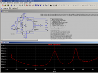
Here is a graph of the voltage drop from input node to output node plotted as a resistance can look like - the output stage can be modelled as the voltage source in series with this resistance, not taking into account the DC offset created.
Attachments
A forum friend have asked, so i have made a bad A to B comparison
I had problems with the switch.... the one broke during the test..so i had doubts and gaps when passing from one amplifier to the other... was the Dx Standard versus Dunlap amplifier.....
http://www.youtube.com/watch?v=EnSWgJQHd7w
Room acoustics are bad... recording also not very good and speaker position not fine....but you have the comparison, hard to perceive things this way.... Dunlap amplifier has more brigth, more focus, almost same bass.. seems a little bit more present.... mid ranges, presence clear, dinamics fine...more focused, more detailed.
Into life audition.... say....not a recording...listening here, despite the awfull acoustics i have in this new room used, the advantage goes very clear to Dunlap amplifier.
How big is this advantage?
Small, alike happens usually, the higher class, higher cost, higher quality amplifiers use to offer advantages that are not THAT BIG.
We can love to listen Dx Amplifier if you have never compared to Dunlap amplifier...after comparison...well...you will notice you will be loosing something because you had in memory the other had reproduced better.
When you reach some good level of quality, the advantage is small... alike formula 1.... advantage is miliseconds.
Sorry... i have trown the switch into the trash box... i have to buy a new one...and a better one... also i cannot produce A to B in this room.
Carlos
- Status
- Not open for further replies.
- Home
- Amplifiers
- Solid State
- Krill - The little amp that might...