Spiny said:To follow up, replaced the outputs Q13,Q14,Q15 and Q16 with a pair of power darlingtons (MJ11015 and MJ11016) Still sounds good and now can run some power without letting the magic smoke out.
Steve if you read this, whats your take on using power darlingtons instead of the output pair? I build rather than run simulations and it still seems to work very well. 😎
Darlingtons will work here. If you use Darlingtons with my board you will need to add jumpers from base to emitter where the drivers would have been.
jmmartins said:
Hi Phil
With R26 I adjusted the bases of Q7,Q10 to 0V (not grounded) and that way i get an offset of about +220mV (in the output).
If I want 0V, output offset, I can achieve that adjusting R26, but that way I get about -220mV in the base of Q7 andQ10
There are 2 offset’s to adjust. The first one (VAS offset) is the collector of Q4 Q6 (base of Q7 and Q10) that should be set to 0V and the second one is the output offset that should be set to 0V with R32 or R33. Now, as I am trying to avoid using R32, I have only one resistor to adjust both - (R26). When I increase the Volts in the bases of Q7 Q10 I increase also the Volts in the output, so I will always get an offset; in the base of Q7 or in the output.
My doubt is: this small VAS offset has a big negative impact in the input transistor pair (Q1 Q2) or not?
Thanks
The offset for the VAS should be set with your preamp or other source attached to the amp input. It is best to adjust the VAS for minimum offset. If this gives an unacceptable offset on the output, you can adjust for a compromise between the two. The preferred solution is the trimmer for the output.
PH104 said:And here some comments on the boards and parts.
***************************************
These comments refer ONLY to the Krill 100W schematic posted in post #1013, page 41 of the “Krill - The little amp that might...”. This is the same schematic linked to in post #9, page 1 of the “Krill construction thread - 100W version”
R1. 220 © as shown is fine. I used 1.0 k© so that the resistances on the inputs of the differential pair each “see” the same resistance to “ground”. Thermally couple Q1 to Q2. I used a dab of epoxy.
R20 is not present on the board. I cut the trace between the +V buss and R60 and soldered in R20 on the bottom of the board.
R9 is shown as connected to –V. On the board it goes to ground. Use about 50 k© for R9 for the 100W version.
D7 on the schematic corresponds to D8 on the board and vice-versa. Same with D9 and D10. D7, D8. D9, and D10 are correctly oriented on the board.
The 10K multi-turn pot is shown on the schematic as connecting in parallel with D102 and D103. On the Krill boards it connects in parallel with D101 and D102. Electrically it makes no difference.
R15 should be 100 k©. R25 is not on the board.
R21 and R22 are 10©/5W, not 10k©.
Q101 and Q102 (the pass transistors in the power supply) should be labeled as Q17 and Q18.
The power supply connections to the output are not shown correctly. The are shown correctly in post #805, page 33 of the “Krill - The little amp that might...” thread for the 50W version.
Hi Phil,
Most of these points have been corrected on the 50W schematic and the 100W schematic. c2cthomas is checking over the 50W schematic and BOM looking for errors. As soon as I hear from him, I will start posting the finalised schematics and BOMs.
Regarding R1; If you have a source that is cap coupled at it's output, changing the value of R1 will have no effect on the input pair's "view" to ground. It will change the HF role off point, but not enough to effect the sound.
One more appointment tomorrow and I should have my results. Hopefully I will be back to answer questions in a more timely manner after that.
Steve Dunlap said:
c2cthomas is checking over the 50W schematic and BOM looking for errors. As soon as I hear from him, I will start posting the finalised schematics and BOMs.
Steve - YGM 😉
Go chase the nurses - it's a lot more fun than talking to the Doctor's!!

Oop's - I forgot that you are married - better not chase the nurses - better listen to the Doctor's. Destroy this message after reading.


A few details...
Voltage gain stage rail voltages: +/- 66VDC.
Output stage rails: +/- 63VDC no-load.
3 pairs of 2SC5220/2SA1943 output transistors at 50 mA idle current.
I'm also using a Toshiba 2SC3381 monolithic dual BJT for the input pair. The voltage gain stage offset is stable plus/minus a few millivolts around 0.
Output stage offset is nulled out using R32 or R33 (I forget which one I had to use).
My Cordell THD analyzer is in pieces for a rebuild right now. Hopefully I'll get in some distortion measurements in a couple weeks.
Krill amplifier
Jmmartins
Tried to contact by e-mail with no avail, perhaps my e-mail didn't reach
you. Is it possible to give me your adress so I can ask you a question in
private?
I'd appreciate
Jmateus
Jmmartins
Tried to contact by e-mail with no avail, perhaps my e-mail didn't reach
you. Is it possible to give me your adress so I can ask you a question in
private?
I'd appreciate
Jmateus
How to take pictures of ur 'scope:
turn off flash!
set camera for closeup (flower setting).
place camera on stable surface.
set timer
wait for picture...
_-_-bear
turn off flash!
set camera for closeup (flower setting).
place camera on stable surface.
set timer
wait for picture...
_-_-bear
Hi Mateus
I tried to reply to your email but something is not working because all of my replies bounce back with an "recipient does not like ..." Do you have another email adress?
My amp is built and working. Later I will post some issues and photos.
I only have a not very good frequency generator and an osciloscope. No distortion analysis equipment.
Martins
Krill amplifier
Hello Martins
Thanks for answering.
I suspect now there is something wrong with my e-mail account, I have
to investigate that.
This is another e-mail adress:
jmateusm@gmail.com
Thanks very much
Hello Martins
Thanks for answering.
I suspect now there is something wrong with my e-mail account, I have
to investigate that.
This is another e-mail adress:
jmateusm@gmail.com
Thanks very much
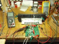
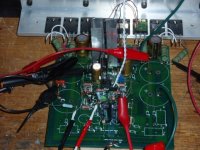
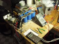
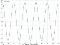
I've made a little more progress on my Krill. Now using 4 pairs of 2SA1943/2SC5200 for output. The scope shots are from a crude set-up with lots of clip leads. The compensation needs some further tweaking but that will wait until the board gets hard-wired into a chassis.
I did some very preliminary tests today with music streamed from KVOD-Denver through my MacBook into the Krill then a small home theater speaker. It sounded pretty good - good enough that I will build the other channel and get the amps ready to play through my regular system. (And Carlos, I have not forgotten for your request of a description of that. I'll do that when I post more listening tests.)
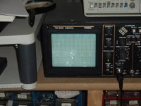
1 Khz sine wave into 8 ohms, 13V RMS.
I did some very preliminary tests today with music streamed from KVOD-Denver through my MacBook into the Krill then a small home theater speaker. It sounded pretty good - good enough that I will build the other channel and get the amps ready to play through my regular system. (And Carlos, I have not forgotten for your request of a description of that. I'll do that when I post more listening tests.)
1 Khz sine wave into 8 ohms, 13V RMS.
Attachments
- Home
- Amplifiers
- Solid State
- Krill construction thread - 100W version