jmmartins
Very professional! I'm finishing up mine now but they will just be on piece of wood for now 🙄 You and Spiny have set a high standard.
Do you have any comments about the sound?
added in edit: What are the supply voltages?
thanks
Very professional! I'm finishing up mine now but they will just be on piece of wood for now 🙄 You and Spiny have set a high standard.
Do you have any comments about the sound?
added in edit: What are the supply voltages?
thanks
Hi Phil
As you know it is not easy say something about the sound because it is a personal taste, but I can tell you I like it. It’s warm and by warm I mean the bass is strong but not loose, the highs are soft but there! I can listen to it all day long without getting tired (and I do that!), but don’t be fooled, if the recording is bad you will hear it!. For me, this is a good thing because I am a bit tired of that “hifi” sound that “sounds” thin and irritating. Stereo image is solid even if I get close to one loudspeaker I can clearly hear the other one.
It is clearly better (to my taste) than all commercial amps I own. It is very different from a chipamp (I own several DIY)! And I’m not saying better nor worst, but different.
No “thump” when “On” and when “Off” it just fades out.
But hey, I wrote these notes without putting some efforts in accuracy, and English is not my native language so …
Supply voltage is +- 50V and +-56V in VAS
J Martins
PH104 said:
added in edit: What are the supply voltages?
thanks
Mine uses a 25 0 25 225VA transformer giving 35.5 0 35.5 DC rails under load. VAS @ 37v
jmmartins wow thats really neat, very professional.
PH104, looking forward to your findings once its up and running
jmmartins said:A very big "thank you" to Steve,
This is an amazing amplifier.
detail:
You're welcome. I'm glad you like it.
originally posted by jmmartins
I can listen to it all day long without getting tired (and I do that!), but don’t be fooled, if the recording is bad you will hear it!.
J Martins -- Thanks for your impressions. That is exactly the kind of presentation I like. My first priority is enjoying the music, the second is getting the nuances out of the recording. I'm not using the Krill front end so I'm very curious how the output stage will change the sound. I'm working on the construction of the complete amps now but taking a little side path to see if I can run the front end open-loop as well as closed loop. And hey -- your English is fine!
J Martins and Spiny -- Thanks for voltage info.
Steve Dunlap -- Congratulations to you also!
c2cthomas -- we better get off our butts and post some listening impressions.

Phil
Question about Power supply
Hello
JMMartins do you have trafo with four secondaries?
I am about to get my Krill up and running this weekend but I haven´t solved my PSU issue.
I have only one dual secondary trafo at the moment and I was thinking to add an external power supply for Steves boards.
On the PSU I will add standard rectifier and some caps + the voltage doubler and from that PSU I will feed both boards. The boards have their own regulation transistors.
Is this a good idea or should I just wire both boards directly from the trafo secondaries?
Hi Jarkaa
My trafo has 2 secondary’s (35 0 35) + (35 0 35), and it’s rated 500W.
In fact I own this trafo for about 4 or 5 years and it was intended for another project that I gave up.
I don’t think you need to build a separate power supply. The one on Steve’s board is very well designed and very close to OP transistors. I would connect the secondary of the trafo to both boards and use the board diodes, capacitors and regulation of the VAS voltage. That way, the only device shared by the 2 channels will be the power transformer. But, of course, Steve is the designer and maybe he can have another idea.
Hi,
the two separate centre tapped secondaries are isolated from each other.
That isolation allows you to build two dual polarity PSUs that are completed isolated from each other.
The two channels of amplification can be attached and they will be completely isolated from each other.
BUT.
as soon as you apply the rule:-
All exposed conductive parts must be connected to Safety Earth, the two channels are no longer isolated.
The Safety rule, which has absolutely nothing to do with the audio performance, has degraded the system performance.
Thanks for the replys.
Maybe I was a little unclear here. My trafo has no center tapped secondaries. It is 2x30V.
So do you still recommend to use that without external PSU.
Jarno
Maybe I was a little unclear here. My trafo has no center tapped secondaries. It is 2x30V.
So do you still recommend to use that without external PSU.
Jarno
So do you still recommend to use that without external PSU.
Yes!
All exposed conductive parts must be connected to Safety Earth, the two channels are no longer isolated.
Of course, but one can never forget safety!
J Martins
Steve --
Is there a way to optimize idle current on the Krill without a distortion analyzer -- at least to a first approximation? You had mentioned that the bandwidth increases as you approach the optimum idle current then decreases past that. Can this be used?
Also, is there any magic to the value of the cap between the bases of the driver transistors (C7)? I have a variety of caps from 1 to 4.7uF in different dielectrics and have some flexibility here.
Thanks
Phil
PH104 said:Steve --
Is there a way to optimize idle current on the Krill without a distortion analyzer -- at least to a first approximation? You had mentioned that the bandwidth increases as you approach the optimum idle current then decreases past that. Can this be used?
Also, is there any magic to the value of the cap between the bases of the driver transistors (C7)? I have a variety of caps from 1 to 4.7uF in different dielectrics and have some flexibility here.
Thanks
Phil
Phil,
I don't remember saying that. The bandwidth does change slightly with the bias setting, but I'm not sure if that can be used to set the bias as these changes occur at a frequency above what most people without specialized equipment can measure. When Thomas gets his finished and brings it over for testing I will look for a method that most of you can use.
The value of C7 is not critical.
PH104 said:Thanks Steve. Sounds like Thomas better get to work finishing his amp, but then so should I. 🙂
Ha-Ha - beat ya Phil!! 😀
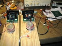
Went over to Steve's today and fired up the amps. The one's I built are 50W versions - but there are two of 'em so I figure that both of 'em together = a 100W "Krill".
These are in "test" stage and I still need to figure out what I'm gonna do for an enclosure to house them in - but give me time - it's coming!
So anyhow - no shielding and no real ground plane other than the circuit trace on the PWB's. Wires running all over the place - stuff just "clipped" together in terms of input and output signals 'cause Steve wouldn't let me solder the O'scope leads to the boards (well - I didn't actually ask him if I could do that - I just assumed he would sort of frown about such a request 🙄 ).
Here's a photo of the amps - I'll post some scope pictures in my next post.
Attachments
c2cthomas said:
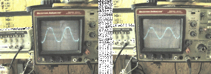
I'll post some scope pictures in my next post.
Ok - left photo is 20kHz signal being driven to soft clipping at around 23V (50W amp).
The right photo is 20kHz at just below clipping.
BTW - the amps ran fairly cool to the touch - even at full output. They did get hot when we ran a 100kHz square wave signal into 'em - but I'll show that in the next post.
Attachments
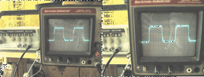
100kHz signal - the left photo is the signal input (ugh) and the right photo is the output of the amp being driven at full output. After about 15 minutes of that little torture the amps were running hot - REAL HOT!
See as how our signal source was so nasty looking I didn't bother running THD test.
See as how our signal source was so nasty looking I didn't bother running THD test.
Attachments
originally posted by c2cthomas
Ha-Ha - beat ya Phil!!
Harrumph! 50W Girlie amps don't count.

Seriously though -- Congratulations! Did you need any compensation cap in the voltage stage? Have you looked at offset drift from a cold start-up? You built exactly as per Steve's schematic (post #1460 in Krill thread) so there's no offset adjustment in output stage, right?
I've almost got one output board done. I'm using a Rat Shack proto board, 4 pairs of o/p transistors per channel. Will post a pic later.
PH104 said:
Harrumph! 50W Girlie amps don't count.
Seriously though -- Congratulations! Did you need any compensation cap in the voltage stage? Have you looked at offset drift from a cold start-up? You built exactly as per Steve's schematic (post #1460 in Krill thread) so there's no offset adjustment in output stage, right?
I've almost got one output board done. I'm using a Rat Shack proto board, 4 pairs of o/p transistors per channel. Will post a pic later.
1. Thanks Dr. Phil 😀
2. Did not use comp cap in the VAS (C2 - not on schema)
3. Tweaked bias to 30mA and let 'em run under load - didn't need resetting after warm-up.
4. Looked at offset and adjusted after bias trim - so the amps were good and warm when we looked at offset (R27). Offset adjustment did not have all that much of an effect except to clean up a little bit of oscillation (not much there). Having all of the output xsistors closely matched (mine were at 87) helped with this.
5. Built per schematic - but I used a 5 turn pot for R26 bias adjustment on one of the amps - and it was much easier to adjust than the amp that had the single turn pot. Recommend multi-turn pot for R26 - a 5 turn pot worked nicely for me.
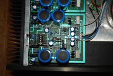
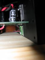
Attached is a photo of the thermal compensation PWB and diode string.
Attachments
- Home
- Amplifiers
- Solid State
- Krill construction thread - 100W version