pinkmouse said:Lookin' good!
I'll second that!! Very tastefully done.. Classic yet modern convience of fan controller...
just you wait untill I get all the wires in there, then it wont look that nice 🙂
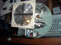
Will the drivertransistors be a problem? This was all I could come up with to mount them and I used conductive paste between the profiles which are bolted to the larger sink.
If the cooling won't be enough then I must try to find something else so I don't fry them...
Will the drivertransistors be a problem? This was all I could come up with to mount them and I used conductive paste between the profiles which are bolted to the larger sink.
If the cooling won't be enough then I must try to find something else so I don't fry them...
Attachments
KMJ
Personally I think they need more heatsinking. I live in a dry area and in summer the heatsinks that normally run cool in winter become quite hot in summer.
Jozua
Personally I think they need more heatsinking. I live in a dry area and in summer the heatsinks that normally run cool in winter become quite hot in summer.
Jozua
Damn! I was already told that but I hoped that he had seen wrong and that I could get a second opinion. But then I'll just have to see what I can come up with. The only available space is above the mainboards and I still need to be able to reach the pots for adjusting gain and offset. Well, when there's a will...Personally I think they need more heatsinking. I live in a dry area and in summer the heatsinks that normally run cool in winter become quite hot in summer.
EDIT
What if I replace the profiles with a solid chunk of aluminum? say 30x30x100mm?
EDIT2
The drivers can be mounted directly on the large sink instead of using the profiles but then only the upper half of the transistor is in contact with the sink. Will that do?
Hi kmj, indeed nice design and this gives me a trigger again to finish the "raditor" once....
Some questions:what is the capacity of the powersupply capacitors?
They seem a little small to me.
Where did you get the nice topplate for the heatsink?
For more cooling to the drivers you could make a new topplate with extension plates bended downwards to mount the U-type alu profile.
Or an extra plate mounted to the flat parts on the sides of the heatsink(near the TO-3's).
Good luck, Loek
Kmj, I'd just try it as it is first, you may well be fine. And if they start getting too warm in the summer, you've had six months to think of a better arrangement. 😉
Each has a capacitanse of 68000uF and can handle 50V. There are a pair of these for each channel so a total of 136000uF.Some questions:what is the capacity of the powersupply capacitors?
topplate? it is two pieces which I salvaged from an amp I bought from China, it had something wrong with it and the warranty was kind of unusable so I scrapped it. Anyway, I took the top and drilled the big hole in it and later had it powdercoated as the rest.Where did you get the nice topplate for the heatsink?
If you litterally mean som part of the heatsink then I bought it on an internetauction for about 45$
For more cooling to the drivers you could make a new topplate with extension plates bended downwards to mount the U-type alu profile.
Or an extra plate mounted to the flat parts on the sides of the heatsink(near the TO-3's).
eeh, pretend that I don't get a word of that sentence and explain a bit more, will you

And build a summerampKmj, I'd just try it as it is first, you may well be fine. And if they start getting too warm in the summer, you've had six months to think of a better arrangement

Jozua said:more heatsinking
Personally speaking, the logic escapes me.
The U-profile looks to be at least 3mm thick, and i gather it is thermally coupled to the cooling duct.
The area between 2 of the extrusions is a cold spot of the cross-section, only better place to put the driver heatsink would be spot in the middle of the duct.
I see 6 bolts connecting the drivers heatsink to the duct, and plenty of space around the U-profile.
If the drivers heatsink is in good(flat) contact with the duct surface i'd try it first, you might be in for a surprise.
Very civilised looking amplifier, KMJ.
If only nice looking girls had a thing for nice looking amplifiers

The individual variations, different people come up with, continue to impress.
(ps: i'd consider a few vent. holes in the powersupply section, iiwy, don't see any)
right on both accounts. However, it isn't a U-profile but two Ls so to speak.The U-profile looks to be at least 3mm thick, and i gather it is thermally coupled to the cooling duct.
It is in flat contact with the exeption of a few mm in the middle where the different pieces meet. But close enough i recon.I see 6 bolts connecting the drivers heatsink to the duct, and plenty of space around the U-profile.
If the drivers heatsink is in good(flat) contact with the duct surface i'd try it first, you might be in for a surprise.
Oh, thank you 🙂Very civilised looking amp, KMJ.
The individual variations, different people come up with, continue to impress.
I do however borrow a lot of idéas from different places.
Edit:
I'm single 😀If only nice looking girls had a thing for nice looking amplifiers
A friend who shares this hobby isn't and he has a lot of preasure from the "govenment" to keep his creations pleasing to look at🙂
See, all it took was a friendly hint😀 Nice work on that amp KMJ. It looks great.Hi guys, I've finally disslocated my thumb
Steen🙂
kjm wrote: I don't get a word of that sentence and explain a bit more, will you
Hi kjm, what i meant was a plate mounted to the back of the U-profile(2 L's) with the dimensions about the size of the heatsink, i am not so handsome in 3-D drawing as Gewa...
But indeed i should try it first as you have build it.
The caps are perfect anyway.
Loek
Hi kjm, what i meant was a plate mounted to the back of the U-profile(2 L's) with the dimensions about the size of the heatsink, i am not so handsome in 3-D drawing as Gewa...
But indeed i should try it first as you have build it.
The caps are perfect anyway.
Loek
KMJ, very nice amp !
One (more) thought about heatsinking: Personally i don't see the point of thermally coupling devices that need cooling to a heatsink that's already hot.
Couldn't you mount the drivers with the l-profiles to the dividing-plate between the powersupply and the amplifier-circuit ?
Just a thought.
I suspect however that it will be fine the way you arranged things now.
greetings,
Klaas
The didiving plate is powdercoated so I think that the thermal conductivity is less than that och the aluminum heatsink. But even if not, the dividing plate is made out of steel and it would be VERY difficult to get a handheld drill to fit and make the necessary holes.Couldn't you mount the drivers with the l-profiles to the dividing-plate between the powersupply and the amplifier-circuit ?
I suspect anyway.
Good Transistor Selection?
Hi folks,
The DC300A is ROCKING in the background and the iron is hot and I am striking. 😀 It's Krell time...
Question: Is my transitor line-up good or should I not use these devices? I don't want to solder these in and have to pull them out of such nice boards later on. I'd wreck the PCB's 'cause they have that nice through-hole contact, which wicks solder so well. 🙂
I need a heads up so let me know. Here is what I'm ready to place in the Pinkmouse driver boards:
Q111 - MJE15028
Q107 Q110 - MJE15031
Q108 Q109 - MJE15030
My outputs are TO3 - MJ15003 & MJ15004
Cheers,
Shawn.
BTW nice amplifier KMJ! Similar heat sink as mine but I won't be using mine for this gig. I'm going down the road without fans blowing. For now anyway, that could change?
Attachments
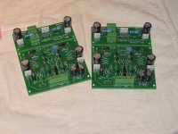
They look fine to me...
...though I would say that, since they are what I used, and they worked perfectly...
Good luck
Stuart
...though I would say that, since they are what I used, and they worked perfectly...
Good luck
Stuart
Re: They look fine to me...
Stuart, that is the exact same line as yours? 😎 Including the outputs? How are you with it over all? Not too much heat for these babies? I guess I'm concened from reading the heat disipation concerns of others. BTW my rails will be +/_ 41 VDC and my R122 - R123 will be upped from 100R to 150R? Is this correct?
Cheers mister laser speed response guy. 😉
Shawn.
Heat...
Yup, I had exactly the same lineup for my first KSA50s.
1) Properly cooled the outputs are more than capable of dealing with the power being asked of them, but yeah, there is going to be a good amount of heat to be dissipated. For longevity big manly heatsinks, or perhaps good fans are a must.
2) 40v rails are within reason and a 10% over voltage on the original Krell would have had them at this level, so not intrinsically a big deal, but see note 1 above ;^)
My speakers (Apogee Duettas) inhale everything the amp has to offer and sound fantastic while doing it, but it is now clear I need to rebuild the things to be closer to the KSA100 level of output, so basically I want more of everything. Not enough hours in the day...
Using the Duettas, compared to an Aleph60, the KSA50 is simply more 'fun', it's like it rocks better than the Aleph. I should add both were built with essentially equivalent specs (Same PSU, heatsinks, bias etc). For speakers with more 'normal' impedance and sensitivity I think the Aleph might be a better suitor...and perhaps one day I'll remake 'em with more of everything too, just for grins...
HTH
Stuart
Re: Heat...More everything
Stuart, I have one 400VA 30-0-30 VAC for each channel and 60,000uF of caps for each channel. I am planning to use only 6 output transistors per channel (MJ15003 x3 & MJ15004 x3). At this stage in the game for my project, what more would you be adding to top it off if it was up to you? Or do you mean more as in up the transistors to MJE15033/34 etc.?
In your reply, please also take into consideration that I am in the queue for KSA100 boards so I can raise the bar next year when that project gets under way.
Thanks again,
Shawn.
Stuart Easson said:...but it is now clear I need to rebuild the things to be closer to the KSA100 level of output, so basically I want more of everything.
Stuart
Stuart, I have one 400VA 30-0-30 VAC for each channel and 60,000uF of caps for each channel. I am planning to use only 6 output transistors per channel (MJ15003 x3 & MJ15004 x3). At this stage in the game for my project, what more would you be adding to top it off if it was up to you? Or do you mean more as in up the transistors to MJE15033/34 etc.?
In your reply, please also take into consideration that I am in the queue for KSA100 boards so I can raise the bar next year when that project gets under way.
Thanks again,
Shawn.
more of everything...
In my case I'm specifically talking about power supply rails, output transistors, heatsinks, ultimately yielding more output power...
I'm not yet convinced the choice of transistors is critical in the final quality of the result, at least when the design is conservative and made for a given level of component performance. So at this point I have no plans to replace the drivers or outputs with newer,"better" versions unless I find I am unable to source the originals, or their intended replacements...
For my KSA50s I used the 'stock' arrangement, i.e. single drivers and double output pairs. In use there's never a sign they are struggling, they simply sound great until they clip...
Luckily Dan & Krell did all the heavy lifting on the design end, by reputation the KSA100 drives low impedance loads well, and I'm not inclined to second guess an expert in his field...I'm going make a close clone of the KSA100, double drivers and quad output pairs. OTOH If I get lazy about drilling all the darn holes, instead of 4 x TO3 pairs I may go for 5 or 6 pairs of the plastic outputs (mj21193/4).
Stuart
- Home
- Amplifiers
- Solid State
- Krell KSA 50 PCB