Hi Tom,
using 1302s then the third device is not optional.
These are 200W devices and using just 2pair of plastic packaged (Tjmax=150degC) devices is inviting trouble.
Add the diodes. They're there to prevent overvoltage pulses (back emf) destroying the output devices.
When assembling Jan's boards you can link out the base resistors. If stability were an issue then reinstating them may help debugging, but at the expense of low impedance load current ability.
If you have board space or it helps with routing then leave pads for the base resistors.
Setting up TO3's
Hi T,
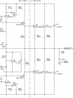
I guess I didn't lay out the previous posts well. I used the schematics only to ilustrate the lack of the resitors connected to the base of the outputs and I still have the question why or why not use them. Why can some designs allow and others not but some both? Very confusing and I'd like to know more without getting off the rails.
I'm using MJ15003/4 three complimentary pairs per channel. I have Mr. Pink's Boards not Jan's.
Since I have three output PCBs with two TO3's on each, where should I place the 1N4004 for each channel? Does it matter? Do folks have a preference.
Cheers,
Shawn.
AndrewT said:Hi Tom,
using 1302s then the third device is not optional.
These are 200W devices and using just 2pair of plastic packaged (Tjmax=150degC) devices is inviting trouble.
Add the diodes. They're there to prevent overvoltage pulses (back emf) destroying the output devices.
When assembling Jan's boards you can link out the base resistors. If stability were an issue then reinstating them may help debugging, but at the expense of low impedance load current ability.
If you have board space or it helps with routing then leave pads for the base resistors.
Hi T,
I guess I didn't lay out the previous posts well. I used the schematics only to ilustrate the lack of the resitors connected to the base of the outputs and I still have the question why or why not use them. Why can some designs allow and others not but some both? Very confusing and I'd like to know more without getting off the rails.
I'm using MJ15003/4 three complimentary pairs per channel. I have Mr. Pink's Boards not Jan's.
Since I have three output PCBs with two TO3's on each, where should I place the 1N4004 for each channel? Does it matter? Do folks have a preference.
Cheers,
Shawn.
Hi KJM, if your drawing is a view on the pins the schematic is OK, only the names are wrong:
the left and right(outside) text in a box has to be P-in and N-in.
The Onsemi drawing is a view on the pins.
Yeah, I remembered that I drew the thing for my friend who has the outputdevices mounted inside the tunnel and the pins sticking out. When looking at my sink and the datasheet I saw that it was wrong but started to think in the way of "his worked, did he change them and did I draw it the wrong way?" and such. It was easily solved with a phonecall thou.
And it seems like I've emigrated to Switzerland 😀FYI, I've added KMJ's amp to my web site under "guest pages" (I'm pretty sure he gave me permission for this). Its kind of rough now but I'm going to add more...I hope. If any of you would like, please email me and we can put your krell up there too; I will add the witty commentary for free!
Typo it seems.I see a lot of Pout and no in. Typo?
Yes, I use the resistors supplied in the partsgroupbuy, the are designated R501 R502 R503 R507 R508 R509 in Pinkmouse's BOM.You intend to use resitors on the base of each output TO3. I have thought the PinkMouse and krell designs did not use the base resitors? I did however see them in Jan's work.
Same type here but only two pairs.I'm using MJ15003/4 three complimentary pairs per channel. I have Mr. Pink's Boards not Jan's.
And my amp is still on the kitchensink waiting to have the groundleads bolted in place and the mainboard connected to the driverboards, not much left in other words. It will however have to wait untill after Xmas since I'll be visiting the folks and that beast weights way to much to bring along on the train.
And as I thought, the casing is a wee bit too small so I will have to have the PSU for the fancontroll either loose or in some way mounted above one of the mainboards and have it removed when adjusting bias.
Why does everything always start to act up when it is time for the wiring? 😀
base resistors...
...are not part of any of the original ksa50 schematics.
They have the beneficial effect of making the output stage into a more predictable, resistive load to the VAS. They also have the less beneficial side effect of making output transistors that are lower in gain get less drive current, ie they compromise the current sharing in the output stage.
The 'catch' diodes can go anywhere convenient, they clamp the output voltage to the supply rails, defending the output stage...
HTH
Stuart
kmj said:Yes, I use the resistors supplied in the partsgroupbuy, the are designated R501 R502 R503 R507 R508 R509 in Pinkmouse's BOM.
That is what those are for! 😕 That removes a question mark for me. Cheers. 🙂
KMJ, you are light years ahead by having such a nice case on hand to use for your design. I am just laying out the metal work for this monster and it seems I have a lot of aluminum to cut and tap. 🙁
A Partsconnexion shipment came in today; a brimful of asha, of the resistor type. Those folks are pretty good.
If my Peckover's metal order is ready tommorow I'm out to the garage to start bringing it all together. My case too is running out of room and I need a little extra space for a special treat...Old School VU meters! I'm trying to get the ones with clipping LEDs. I think this amp needs 'em in a bad way. I don't need fans so I have to use something cool? 😀
Jah,
Shawn.
Attachments

NUTTTR said:Bit of a run down:
This amp does ~ 130w RMS class A into 4 ohms (Yes, that's 130w/channel), at 4 ohms it runs into A/B before running out of RMS, however on 8 ohm, it is 100% class A the whole way 🙂
Aaron
Hi Aaron,
what are your rail voltages and what component changes did you make - excluding the higher voltage caps?
Thanks Harry
oooh, I want some of those! Wouldn't fit thou but I still want them...Old School VU meters!
Harry3 said:
Hi Aaron,
what are your rail voltages and what component changes did you make - excluding the higher voltage caps?
Thanks Harry
Hi Harry,
I *think* from memory my rail voltages are ~38v. I've used a LOT of bias (power drain @ idle is 770w from 240v!)... It does warm the room up. My heatsinks are pretty big and fan cooled in a tunnel form. As for parts I used MJ21193/94 on the outputs (5 pairs per channel), I think the others were 15030 or 15032/33 or 34? I what (the drivers) are, but all the components I chose were close to the originals as I could get, with modern technology 🙂 I even got a full set of Dale resisitors, just like the originals! I've used 2x800va toroids in this amp, they are completely monoblock, down to the power point! I've used more capacitance too 132,000uf/channel. All the wiring is thick, and I used 10w 0.68ohm resistors on the outputs (Thanks Stuart!). In all seriousness, it does get hot, but it's thermally VERY efficent. Even when the room is at 30deg the outputs run a max of 62deg (on the hottest points of the case of the TO-3). All the outputs are hard-wired too, It'll be a pain to replace if they go!
However: My time with the amp has been awesome, i'm not going to build anything to replace it, in all seriousness, it's a VERY VERY nice sounding amp. I used Jan's original boards (with the pot's that are wired wrong, just bridged the incorrect links). Sounds LOVELY IMHO!
[edit - as my memory serves me (not well) it does ~136wRMS into 4 ohm - but I run it in 6 ohm - which means class A ALLL the way to full power! Yes, it's a LOT of heat, but it sounds good 🙂]
Aaron
jacco vermeulen said:
Ditto from the winter zone.
You probably wish you had my amp there then!! LOL! In summer it truely heats the room a significant amount!
Hi Nuttr,
can you clarify what bias current you have decided to set up your amps at?
can you clarify what bias current you have decided to set up your amps at?
130w RMS class A into 4 ohms
I run it in 6 ohm - which means class A ALLL the way to full power
seem to indicate three different quiescent currents.power drain @ idle is 770w from 240v
AndrewT said:Hi Nuttr,
can you clarify what bias current you have decided to set up your amps at?
seem to indicate three different quiescent currents.
Hi Andrew,
Yes, sorry, it should have been 130wRMS @ 4 ohms, but not ALL class A. To be honest, i forget the bias voltage, although i *think* it was...
Ah, found it:
Well, my amp is still running 100% - just made some changes - now both left/right are "fin to fin" to create a wind tunnel effect... 4 x 8cm panaflow fans running @ 8v, definately quieter than the 6 that were there before! I'm still running high bias (optimised a little - i'm running ~5 ohm speakers!)
Obviously the "furthest" bank of transistors are running warm (5 pairs)... I noticed posts previously about the max temp of transistors Tj - what's the "safe" range to keep it in? I'm running +-36Vdc... ~450mv of bias at the moment...(per device)...
Furthest set is hitting about 65 deg on the hottest part of the TO-3 casing (i.e. RIGHT near the dye!)...
So at the moment I have ~460mv bias (from memory) as I upped the fan speed with better fans...
To give you an idea how it 'all started' (Parts to make ~ 5 channels, not all mine!)
http://www.diyaudio.com/forums/attachment.php?s=&postid=581416&stamp=1109079992
LOL
I believe that is right, once i find (or can someone post it?) the class A calculator I can verify if those results are right. I believe it's actually 36v rails, and they are SOLID. Do not move a 0.1, at all times!
Do those figures add up? I've previously posted this stuff up, but for the life of me I cannot find it!
Aaron
[edit - As i remember my dissapation as heat was between 250-300w/channel 😀]
Hi,
no, it does not all add up.
130W ClassA into 4r would require Iq=4A (already discounted).
Full ClassA into 6r would require Iq=2.9A. (100W ClassA into 6r)
770W for two channel implies Iq approaching 5A.
250W for one channel on 36Vdc is Iq=3.47A
300W for one channel on 36Vdc is Iq=4.17A.
Standard 140W from 37Vdc is Iq=1.9A (57W ClassA into 8r)
So i found the spreadsheet!
Excellent, I found the sheet.
Attached is what I am pretty certain are my exact spec's. Speakers provide ~5.* ohm load, took 5 ohm as the value as it's closer to 5 than 6, and now I know why i set it up the way I did! The picture tells all... I do lose power in other areas than *just* the biasing... The bridge rectifiers seem to get pretty warm (on their heatsinks ~60deg. Plus fan controller (25w)...
🙂
It's been quite a while since i've had to look at any of this, and my memory is shadier than a tree!
[edit - i've done the maths, i've got 38v rails, not 36. That does change things a little 🙂 I'm now 98.3325% sure this is right!]
Attachments
Re: So i found the spreadsheet!
Do you recall the part number used for the rectifier or the amperage rating? I'm curious and was thinking of changing the ones I was going to use to something bigger.
Cheers,
Shawn.
NUTTTR said:... The bridge rectifiers seem to get pretty warm (on their heatsinks ~60deg. Plus fan controller (25w)...🙂
Do you recall the part number used for the rectifier or the amperage rating? I'm curious and was thinking of changing the ones I was going to use to something bigger.
Cheers,
Shawn.
rectifiers...
Shawn,
I used 25 amp 250piv epoxy filled aluminium block style...but while the ratings are important, even with a 'big' rectifier heatsinking is essential.
Considering the 'average' (ie best) case 2 of the 4 diodes in the bridge are always turning on, and dropping ~0.7v each at whatever current you are running, with 4A for two channels your bridge dissipates 6w minimum. I'd guess (based on how hot the darn thing gets) the non-linear charging pulses that occur in a real rectifier and smoothing cap situation double that.
For my ksa60 I used a 3"x4" piece of 3/16" (4mm) aluminum (that also served to connect the big caps to each other) as the rectifier heatsink. While I can touch it, it's warm approaching hot. Next time I am planning to use a real heatsink...
HTH
Stuart
I'm very certain i've got the same 25amp Bridges too (thanks Stuart again!). They do put out a LOT of heat (surprisingly). I don't know what the rating of my heatsink was that I used, but without a heatsink they got VERY hot VERY fast 🙂
Obviously i'm running lots of current, so nice and toasty!
Obviously i'm running lots of current, so nice and toasty!
Power Supply
Thanks folks for the replies. I'm rethinking my power supply for each channel now to: 8x10,000uF 63V and a 50amp bridge with some heatsink love on it, or possibly mount it to the chassis. I have the 400VA 30-0-0-30 Plitron x 2 (+/-41VDC)and I will etch a new PCB to hold the caps and keep the other set for another project. I think "over the top" on everything is the way for me to go on this amp.
I am now thinking of extending the chassis deeper and adding another set of heatsinks to the case? If I can the additional extrusions to extend the case will each Pink Driver PCB drive 4 pairs of outputs? MJ15003/4
Will using more outputs allow them to bias at lower current with equal result? Is the 400VA good enough to handle the expansion? What is the predictable Class A performance of my set up? BTW, I'm not going to buy new toroids but the caps I can get cheap.
I'm pretty much ready to start cutting metal so now is the time to sort it. I don't want to regret the build effort later on with, "what If I did this and what if I did that".
Thanks for the input,
Shawn.
- Home
- Amplifiers
- Solid State
- Krell KSA 50 PCB