Pinkmouse posted the schematic here: https://www.diyaudio.com/community/threads/krell-ksa-50-pcb.31077/page-85#post-633428REPEAT:
Would anyone have the schematic and BOM handy for the Pinkmouse boards so I don't have to search through 468 pages? Pleeeaaase. 🙂

"if your current on 3 pairs is 1.5A, then the amplifier will work in class A up to this current value, and then it will switch to class AB ..."
Actually is the bias is 1.5A on a push-pull design, it is expected to leave the Class A region at about 3 amps peak.

Actually is the bias is 1.5A on a push-pull design, it is expected to leave the Class A region at about 3 amps peak.
Am I right in thinking the power into 8r will be around 17watts RMS Class A?"if your current on 3 pairs is 1.5A, then the amplifier will work in class A up to this current value, and then it will switch to class AB ..."
Actually is the bias is 1.5A on a push-pull design, it is expected to leave the Class A region at about 3 amps peak.
Ok, why not take into account a driver that practically dies at an input voltage RMS of more than 1 volt, regardless of the current of the output transistors?"if your current on 3 pairs is 1.5A, then the amplifier will work in class A up to this current value, and then it will switch to class AB ..."
Actually is the bias is 1.5A on a push-pull design, it is expected to leave the Class A region at about 3 amps peak.
Last edited:
Thank you, thank you, thank you!
And thank you! All the original wiki files are gone and all the information I had on hard drives are in storage.Pinkmouse posted the schematic here: https://www.diyaudio.com/community/threads/krell-ksa-50-pcb.31077/page-85#post-633428
Troy,And thank you! All the original wiki files are gone and all the information I had on hard drives are in storage.
I saved a copy of the building guide wiki back in 2007. The links are no longer functional due to all the changes to diyaudio.com since then, but it still contains useful information.
Attachments
Same here, a friend found one in the garage.Arise from the dead...
Well actually like most of the really good "old school" amplifiers you can't kill them and they last forever..
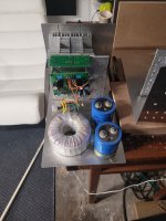
Yesterday an old friend gave me his pinkmouse "kit" to assemble. Chassis, PCB's, Toroid, and components.
My original documentation is several hard drives back and for the most part lost.
Would anyone have the schematic and BOM handy so I don't have to search through 468 pages? Pleeeaaase. 🙂
Attachments
KSA-250 is a much more complex circuit. Remember that KSA50 is one of Dan's early designs. You also want to build the MK2 version of the KSA50, not tje plain ole KSA-50 early version. It's much more stable and sounds better than the original I have built a half dozen of them over the years. The last one I built had 6 output devices and could generate 90 wpc before clipping it could also easily drive 2 ohm loads. All my later builds used the Pinkmouse boards and I built the first one from his boards to verify the boards worked. If you go back through the original build post you will find me there... There is also a calculator there you can use to set bias level based on the number of outputs. BTW, It's an extremely stable amplifier when constructed correctly. If I can find them I'll post some pictures tomorrow...oVery interesting. I wonder how the KSA-250 differs from this. more output transistors for sure but....
Zero 😎
Copying the Pinkmouse boards would be highly beneficial!! They work perfectly. This sort of thing doesn't need redesign, just more boards made the same as his.As I see it, it will be single sided (easier for the diy-people) 😉
I contacted PinkMouse a while back and he said that the gerbers were lost in a crash.Copying the Pinkmouse boards would be highly beneficial!! They work perfectly. This sort of thing doesn't need redesign, just more boards made the same as his.
Someone with more skills than me would probably be able to recreate them
I will search my plethora of ksa 50 data and see if by chance he sent it to me. I may also have a couple of extra boards... some place...I contacted PinkMouse a while back and he said that the gerbers were lost in a crash.
Someone with more skills than me would probably be able to recreate them
Hi,
Could someone help me to locate the post with final version of PCB?
Wish to see the two versions,[ Jan & Pinkmouse]
Thank you,
Sumesh
Could someone help me to locate the post with final version of PCB?
Wish to see the two versions,[ Jan & Pinkmouse]
Thank you,
Sumesh
I ordered Pinkmouse PCBs in May 2021, so I must have the gerbers somewhere...I'll have a look and post them.
I'm in the UK and I have ten Pinkmouse PCBs doing nothing if someone wants a couple.
Edit: I've attached the files 🙂
I'm in the UK and I have ten Pinkmouse PCBs doing nothing if someone wants a couple.
Edit: I've attached the files 🙂
Attachments
Last edited:
Beat me too it 🙁and here it is, organized exactly as you need to upload it for fabrication
🤣

It is unbelievable how the KSA forums just continue to give year after year,..... Amazing!
I just found the gerbers for both KSA50 boards. But I don't really recommend using the old one. Just the Pinkmouse board as it is much easier to mount. Not going to post it as someone else already did.
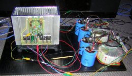
Here are is an image I found of the very first KSA50 I built using the original boards. This image IS DATED March 20, 2005. I will post more of my final build of the KSA50 as I find them.
Here are is an image I found of the very first KSA50 I built using the original boards. This image IS DATED March 20, 2005. I will post more of my final build of the KSA50 as I find them.
Attachments
- Home
- Amplifiers
- Solid State
- Krell KSA 50 PCB