A transformer with 45Vac secondaries seems too high, for this amp.
If I remember correctly the transformers used for 50W Class A, were around 2x28Vac or 2x35Vac. The VA was 400-500 per channel.
You need to look through this thread to confirm.
If I remember correctly the transformers used for 50W Class A, were around 2x28Vac or 2x35Vac. The VA was 400-500 per channel.
You need to look through this thread to confirm.
Yes that’s about right
I have moved on from those original transformers and continuing my search for reasonably priced units of more appropriate specs.
I have moved on from those original transformers and continuing my search for reasonably priced units of more appropriate specs.
Arise from the dead...
Well actually like most of the really good "old school" amplifiers you can't kill them and they last forever..
Yesterday an old friend gave me his pinkmouse "kit" to assemble. Chassis, PCB's, Toroid, and components.
My original documentation is several hard drives back and for the most part lost.
Would anyone have the schematic and BOM handy so I don't have to search through 468 pages? Pleeeaaase. 🙂

Actually, the factory xformer was either 2 x 36 volts, or 2 x 38 volts. But it also only had four output devices. When I built mine, early on in the Pink Mouse section, it had single Primary - dual secondary toroid of 2 x40 volts at something like 10 amps per secondary. But I also had six output devices per channel. Somewhere in the long thread is a calculator to determine bias setting depending on number of devices, and DC rail voltage. And I used that to calculate bias setting. Mine was forced air cooled and always sounded awesome.A transformer with 45Vac secondaries seems too high, for this amp.
If I remember correctly the transformers used for 50W Class A, were around 2x28Vac or 2x35Vac. The VA was 400-500 per channel.
You need to look through this thread to confirm.
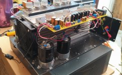
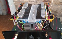
I have also resurrected my KSA50 Chinese copy monsters.
I found an old heatsink from a failed Aleph 5 and built the psu into the lower box.(25vAC)
The cooling fan is usb powered and on the lowest of the 3 speeds drops the heatsink temp by 20C.
I found an old heatsink from a failed Aleph 5 and built the psu into the lower box.(25vAC)
The cooling fan is usb powered and on the lowest of the 3 speeds drops the heatsink temp by 20C.
Attachments
Hello!I have also resurrected my KSA50 Chinese copy monsters....
What is the supply voltage of the amplifier?
It's +- 36v.Hello!
What is the supply voltage of the amplifier?
I don't need maximum possible output as it's only driving a pair of GRS planar mid-tweeters in my reworked ML Aeons.
I suggest:
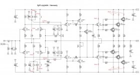
1. put jumpers instead of R11R12 - this balances the operation of the input differential stage when working with a difference signal, and also reduces the effect of the Miller capacitance of the input transistors on the input signal.
2. reduce the resistors R7R8 to 1 kOhm - this will increase the current through the zener diodes DW1DW2 and, accordingly, improve the stabilization of the input differential stage.
3. reduce R15R16 to 36 kOhm and reconnect them to the zener diodes DW1DW2 of the differential stage - this will reduce the penetration of power ripples to the inverting input of the amplifier
4. Disconnect the connection point of the R25R26 resistors from the amplifier output - this balances the complementary output stage in terms of current and significantly (at least twice) reduces amplifier distortion, as well as crossover distortion.
Everything can be seen from the visualization in the attachment:
Attachments
Last edited:
It will also improve the transient characteristics of the amplifier by reducing the sensitivity of increasing the resistor R33 to 1.2 k ohm.
I don't need maximum possible output as it's only driving a pair of GRS planar mid-tweeters in my reworked ML Aeons.
This amplifier is very good for this, Den Dagostino added Q5Q7 transistors to the Leach circuit model, due to which he eliminated the influence of C5C6 Miller correction on the input stage, thereby making it very linear before NFB coverage.
Why only 66ma through the opts? I'm running at .5amp per transistor.I suggest:
1. put jumpers instead of R11R12 - this balances the operation of the input differential stage when working with a difference signal, and also reduces the effect of the Miller capacitance of the input transistors on the input signal.
2. reduce the resistors R7R8 to 1 kOhm - this will increase the current through the zener diodes DW1DW2 and, accordingly, improve the stabilization of the input differential stage.
3. reduce R15R16 to 36 kOhm and reconnect them to the zener diodes DW1DW2 of the differential stage - this will reduce the penetration of power ripples to the inverting input of the amplifier
4. Disconnect the connection point of the R25R26 resistors from the amplifier output - this balances the complementary output stage in terms of current and significantly (at least twice) reduces amplifier distortion, as well as crossover distortion.
Everything can be seen from the visualization in the attachment:
I deliberately made the current smaller, tk. in this case, it can be seen that in Dena Daggostino version, the connection of the R25R26 resistors worsens the symmetry of the complementary output stage, and therefore it is necessary to increase the current through the output transistors in order to increase the linearity and reduce the effect of crossover distortion.Why only 66ma through the opts? I'm running at .5amp per transistor.
if R25 R26 is disconnected from the output, the driver stage starts working in class A and becomes more symmetrical and there is no need to additionally increase the current through the output transistors. Please note that as the temperature of the bipolar transistor crystal increases, its transfer coefficient decreases, and for the PNP transistor this angle of inclination differs from the NPN transistor - this leads to an increase in the even harmonic, but not to an improvement in the quality of sound reproduction.
P.S. with the RW36 you can wind up the output stage current to your liking in terms of sound from the speaker system.
Last edited:
Yes, damn it, not worse ...what do you not understand from what is written above?
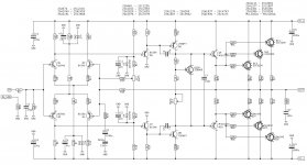
The shown clone of one of the first Krell circuits is a class AB amplifier that can operate in class A, the difference will be only in the output power, I hope you can guess in which case the power will be 1/3 less. (50 in the name of the circuit is the power of 50 watts in class A)
It was later that Dan installed the unit with the "Super-A" mode.
What are the doubts?
P.S. krell KSA50 Class A Power Amplifier Board, Gold Sealed Class A Class A and Class B Switching Power Amplifier Board (https://www.aliexpress.com/item/1005001572467180.html)
Last edited:
I LOVE my KSA50 (Pinkmouse) just the way it is. Its still my best amp for the past 15 years....
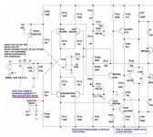
Sorry I posted the wrong schematic. The one below is closest I can find since the seller didn't supply one.Yes, damn it, not worse ...what do you not understand from what is written above?
The shown clone of one of the first Krell circuits is a class AB amplifier that can operate in class A, the difference will be only in the output power, I hope you can guess in which case the power will be 1/3 less. (50 in the name of the circuit is the power of 50 watts in class A)
It was later that Dan installed the unit with the "Super-A" mode.
What are the doubts?
P.S. krell KSA50 Class A Power Amplifier Board, Gold Sealed Class A Class A and Class B Switching Power Amplifier Board (https://www.aliexpress.com/item/1005001572467180.html)
I have removed Q7 & Q8.
Why would you think an amp with three pairs of output transistors would be used in B or AB? Obviously it will run in pure class A until the current exceeds the quiescent current of 1.5a.
Attachments
ok, not quite clear Q7 Q8? from what scheme?Sorry I posted the wrong schematic. The one below is closest I can find since the seller didn't supply one.
I have removed Q7 & Q8.
Why would you think an amp with three pairs of output transistors would be used in B or AB? Obviously it will run in pure class A until the current exceeds the quiescent current of 1.5a.
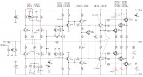
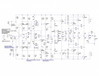
Now we look at the scheme that you now have in the attachment:
1. I indicated the value of the current through the zener diode, which is indicated on your diagram, but this value is obtained at a supply voltage of + - 40 volts, and you have + - 36 volts, therefore the current will be much lower, and it is important that it is not lower than the consumption current diffcascade, otherwise it makes no sense. To do this, you need to reduce R108R109 - see my current map posted earlier.
2. R112 and R113 instead of them, it is better to put jumpers, the reason was also previously voiced, and Den himself reduced these resistors to 10 ohms in later versions of the circuits.
now by class of amplifier - in class B or AB, an amplifier is needed to get a lot of power for powerful speakers,
For the rest, in principle, it is, if your current on 3 pairs is 1.5A, then the amplifier will work in class A up to this current value, and then it will switch to class AB ...
Also pay attention to the location of the correction capacitors C107 and C108, since this is a clone, the clone developer intentionally rearranged these capacitors to get rid of the Мiller correction, but at the same time unsuccessfully placed them shorted to the power rails, where there is a lot of interference that can penetrate the input output stage. I don’t really like this arrangement of the correction - it worsens the transient characteristics of the amplifier, because additional current is required from the voltage amplifier to pump these capacitors in the high-frequency range.
Attachments
REPEAT:
Would anyone have the schematic and BOM handy for the Pinkmouse boards so I don't have to search through 468 pages? Pleeeaaase. 🙂
Would anyone have the schematic and BOM handy for the Pinkmouse boards so I don't have to search through 468 pages? Pleeeaaase. 🙂
https://www.diyaudio.com/community/attachments/pinkmouse-bom-pdf.830571/Here it is attached.
You're welcome.
Do not hesitate to ask me. I will be available to help you if I can and know. Remember though, my present capabilities are limited🙁, but I learn quickly and a lot.🙂
I am also attaching Pinkmouses' BOM. Both of these files are somewhere in this thread but I wouldn't let you search for a needle in a hay stack. 😉
Which board do you use?

- Home
- Amplifiers
- Solid State
- Krell KSA 50 PCB