Thank you Neychi I will change them.
It looks like mouser and RS components do not list them so it must be those I got from cricklewood electronics because no components come from ebay for that reason.
I will check for Sanyo or toshiba.
Is Sanyo or Toshiba best or does it not matter.
Sanyos are direct substitution, almost identical.
Originals : https://www.diyaudio.com/forums/swap-meet/328924-fs-various-semiconductors-opamps.html#post5578145
(compare the SOA of A1011/C2344, A1837/C4793, A968/C2238)
Hi Jacco have you still got 4 x toshiba 2SA968 and 4 x toshiba 2238 transtors please.
how much would it cost for these and to post them to the UK thanks.
Sanyos are direct substitution, almost identical.
Thanks neychi I am having trouble finding Sanyo 2SA 1011/2SC2344 in stock at any of my UK suppliers.
I have asked jacco if he still has original transistors for sale.
Member
Joined 2009
Paid Member
I'm afraid I do not have good news for you. These are definitely not original Toshiba transistors, but some generic Chinese type. Identical are selling on ebay. Today it is almost impossible to find new, original Toshibas. It would be better to try to find replacement transistors like Sanyo 2sa1011 / 2sc2344 or Toshiba 2sa1837 / 2sc4793.
+1
I never buy transistors (FETs, premium caps, or anything expensive) from China, even better, avoid eBay because you simply can't be sure. Big suppliers like Digikey have internal processes and programs to validate the parts and suppliers they sell.
...It would be better to try to find replacement transistors like Sanyo 2sa1011 / 2sc2344 or Toshiba 2sa1837 / 2sc4793.
The Toshibas work well in my PCB. 😉
The Toshibas work well in my PCB. 😉
The genuine Toshibas usually have this habit to work well 😀
I used all Motorola devices in all my KSA-50 builds, except for the iput quad which was 2SA-2SC semis.
Mark
Mark
Hi Jacco I have sent you a messageOriginals : https://www.diyaudio.com/forums/swap-meet/328924-fs-various-semiconductors-opamps.html#post5578145
(compare the SOA of A1011/C2344, A1837/C4793, A968/C2238)
Awhile back I received these populated KSA-50 clone boards from a friend of a friend who was moving and had repurposed the power supply. Supposedly they work just fine. This will be my second class-A build, the first was a 10W JLH, so this is a pretty big step up and I’d appreciate any input on my proposed clone.
Power supply
Keeping it standard. 2 x 400 VA with dual 24V secondaries (probably AnTek) and 2 x 51,000 uf Kemet capacitors per channel. Anyone know these Kemet caps, any thoughts?
Heat management
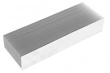
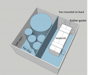
I’d like to use two of the heatsinks below fin to fin and bracketed together on the top and bottom to create a heatsink tunnel. I’ll pull the air out the back of the chassis with an 80mm noctura fan mounted to the outside. I’ll need a few angle brackets to hold the heatsink tunnel horizontal and I’ll use rubber washers to reduce vibration noise. The fan comes with a gasket and I’ll cut an appropriate gasket for the heatsink on the inside. To power the fan, I’ll use a separate small 12V transformer and a variable power supply (LM317). This should allow me to dial in the fan speed or control it with a thermistor. I can use that same transformer with a thermal switch to rig up a thermal shutoff as well, like a trigger switch.
Chassis
In order for audio gear to leave my home office space it must fit into one of two 7” by 21” cubbies in media consoles (open on the back) and leave enough space for a small preamp and phono stage of some sort. I’ll look around, but I’m prepared to build my own chassis at about 12” wide, 12” deep and 6” tall. I’ll follow the lead of grimberg. Between the chassis and heatsink there will be lots of drilling and tapping…
Soft start
Plenty of cheap prebuilt options on ebay or if the quality of parts is a concern, I’ll use the diy audio softstart v3 board.
THANKS!
Joe
An externally hosted image should be here but it was not working when we last tested it.
Power supply
Keeping it standard. 2 x 400 VA with dual 24V secondaries (probably AnTek) and 2 x 51,000 uf Kemet capacitors per channel. Anyone know these Kemet caps, any thoughts?
Heat management
I’d like to use two of the heatsinks below fin to fin and bracketed together on the top and bottom to create a heatsink tunnel. I’ll pull the air out the back of the chassis with an 80mm noctura fan mounted to the outside. I’ll need a few angle brackets to hold the heatsink tunnel horizontal and I’ll use rubber washers to reduce vibration noise. The fan comes with a gasket and I’ll cut an appropriate gasket for the heatsink on the inside. To power the fan, I’ll use a separate small 12V transformer and a variable power supply (LM317). This should allow me to dial in the fan speed or control it with a thermistor. I can use that same transformer with a thermal switch to rig up a thermal shutoff as well, like a trigger switch.
An externally hosted image should be here but it was not working when we last tested it.
Chassis
In order for audio gear to leave my home office space it must fit into one of two 7” by 21” cubbies in media consoles (open on the back) and leave enough space for a small preamp and phono stage of some sort. I’ll look around, but I’m prepared to build my own chassis at about 12” wide, 12” deep and 6” tall. I’ll follow the lead of grimberg. Between the chassis and heatsink there will be lots of drilling and tapping…
Soft start
Plenty of cheap prebuilt options on ebay or if the quality of parts is a concern, I’ll use the diy audio softstart v3 board.
An externally hosted image should be here but it was not working when we last tested it.
THANKS!
Joe
Whoops, doesn't look like my image hosting worked. I'm new to this. Attached below. Thanks.
Attachments
Last edited:
Awhile back I received these populated KSA-50 clone boards from a friend of a friend who was moving and had repurposed the power supply. Supposedly they work just fine. This will be my second class-A build, the first was a 10W JLH, so this is a pretty big step up and I’d appreciate any input on my proposed clone.
An externally hosted image should be here but it was not working when we last tested it.
Power supply
Keeping it standard. 2 x 400 VA with dual 24V secondaries (probably AnTek) and 2 x 51,000 uf Kemet capacitors per channel. Anyone know these Kemet caps, any thoughts?
Heat management
I’d like to use two of the heatsinks below fin to fin and bracketed together on the top and bottom to create a heatsink tunnel. I’ll pull the air out the back of the chassis with an 80mm noctura fan mounted to the outside. I’ll need a few angle brackets to hold the heatsink tunnel horizontal and I’ll use rubber washers to reduce vibration noise. The fan comes with a gasket and I’ll cut an appropriate gasket for the heatsink on the inside. To power the fan, I’ll use a separate small 12V transformer and a variable power supply (LM317). This should allow me to dial in the fan speed or control it with a thermistor. I can use that same transformer with a thermal switch to rig up a thermal shutoff as well, like a trigger switch.
An externally hosted image should be here but it was not working when we last tested it.
Chassis
In order for audio gear to leave my home office space it must fit into one of two 7” by 21” cubbies in media consoles (open on the back) and leave enough space for a small preamp and phono stage of some sort. I’ll look around, but I’m prepared to build my own chassis at about 12” wide, 12” deep and 6” tall. I’ll follow the lead of grimberg. Between the chassis and heatsink there will be lots of drilling and tapping…
Soft start
Plenty of cheap prebuilt options on ebay or if the quality of parts is a concern, I’ll use the diy audio softstart v3 board.
An externally hosted image should be here but it was not working when we last tested it.
THANKS!
Joe
Hi Joe I have got these kemet 51,000 uf capacitors and was told they will be fine.
I purchased my soft start boards from ebay item number 263727499334 High power 40A for class A amp.
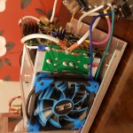
Nothing is connected or tested yet as its a ongoing project.
Hi looking for some help please as I made a mistake on my amp build.
My output transistors shorted because I used a conector which was too large and moved shoting out my B+ to out on my output transistor pcbs.
Which parts may I have damaged and how do I check please.
My output transistors shorted because I used a conector which was too large and moved shoting out my B+ to out on my output transistor pcbs.
Which parts may I have damaged and how do I check please.
Attachments
I have got +48v /- 48v at pcb if I try to adjust dc offset lowest I can get it is 1.6v.
Tried to connect a speaker but it makes transformer buzz.
Output transistors dont seem to be getting warm
Tried to connect a speaker but it makes transformer buzz.
Output transistors dont seem to be getting warm
Dave,
Did you test the main board before connecting the output devices? If you have not done so, that should have been the preliminary test before attaching the output devices. The main board should be fully functional and you can even connect a speaker and play it at low volume.
Did you test the main board before connecting the output devices? If you have not done so, that should have been the preliminary test before attaching the output devices. The main board should be fully functional and you can even connect a speaker and play it at low volume.
Dave,
Did you test the main board before connecting the output devices? If you have not done so, that should have been the preliminary test before attaching the output devices. The main board should be fully functional and you can even connect a speaker and play it at low volume.
No I didn't I connected it all up and tried to afjust dc offset but can'tget it lower than 1.6v.
I get +48v and -48v B+ is 1.8v.
Also if I connect a speaker the cone of speaker is pushed out due to 1.6v dc voltage I take it.
My mains transformer buzzes when I connect a speaker and my speaker protection kicks in.
Also if I connect a speaker the cone of speaker is pushed out due to 1.6v dc voltage I take it.
My mains transformer buzzes when I connect a speaker and my speaker protection kicks in.
Last edited:
I suggest you remove the main board from the heat sink assembly, connect it to the power supply, start it and debug it until you can hear music playing through a speaker attached to it.
The power output stage drivers should be loaded by resistors of about 25R, so you don't need the output transistors attached to be able to have a fully functional main board.
It helps if you post the schematic matching the PCBs you used.
The power output stage drivers should be loaded by resistors of about 25R, so you don't need the output transistors attached to be able to have a fully functional main board.
It helps if you post the schematic matching the PCBs you used.
I suggest you remove the main board from the heat sink assembly, connect it to the power supply, start it and debug it until you can hear music playing through a speaker attached to it.
The power output stage drivers should be loaded by resistors of about 25R, so you don't need the output transistors attached to be able to have a fully functional main board.
It helps if you post the schematic matching the PCBs you used.
Thank you for your help I will try this.
It does play music for a couple of seconds but output protection kicks in.
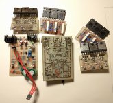
These are the pcbs I am using meant to be exact copies of original krell ksa 50 mk11.
I am not sure about the ground on this amp if I have got it correct.
Should the pcb ground go to the same ground as speaker or to chassis ground or should the be a resistor between speaker ground and pcb ground.
I need to solve the problem of 1.6v dc at speaker and then I think it will work ok.
Thanks for any help.
- Home
- Amplifiers
- Solid State
- Krell KSA 50 PCB