Yes, 20x40mm and 40x80mm, that is correct.
It is as you say, an MS Excel spreadsheet is what I/he needs.
I did however make one misstake earlier. The spreadsheet is only used to collect the data for the text, such as spelling and small or capitol letters. NOT font and size.
What I'm trying to say is that all badges in the same batch (size) will have the same font and textsize, we only have to note which ones that we don't want to have logos (your leach for example).
As long as the physical size of the badge is the same and the layout of the mountingholes also are that, then he'll charge the same even if there's some extra work included.
kmj said:
The text-part can be altered and still made in the same batch.
So, badges with the "KSA-50" substituted for "KSA-100" can be made in the same batch.
So, If anyone want badges for the future KSA-100 projects that is OK too.
Okay, I would like to increase my order to 2 small badges for KSA-50 and 2 small badges for KSA-100.
Robert
Ok, I'm keepning track of the orders at home instead of posting all the time. I will however update every now and then.
Hi, My friends Klone is starting to look finished and ofcourse I'm glad to soon be able to see/hear a finished amp. And I'm not the least jealous even thou I have finished the casing and nothing else.... I'm not... definately not.... Well, I tried to convince myself... That speedy bastard 
Aaaanyway!
On the mainboards there are four solderpoints, one for signal-in and three groundpoints. my thought is to put the signalground on the left, but what of the two in the middle? Just connecting them to starground or what?
Aaaanyway!
On the mainboards there are four solderpoints, one for signal-in and three groundpoints. my thought is to put the signalground on the left, but what of the two in the middle? Just connecting them to starground or what?
Yes, straight to starground. They are separate grounds for signal and power, so don't really want to mix.
Hi Kmj,
are they the pinkmouse PCBs?
The three connections labelled GND are:-
left, power ground (dirty) to power ground elsewhere.
middle, signal ground (clean) to central star ground, beside the power ground possibly.
right, signal ground (clean) to RCA input socket ground.
I would suggest keeping the RCA ground and input signal on adjacent pins to minimise the loop area and keep some semblance of interference rejection.
left, power ground (dirty) to power ground elsewhere.
middle, signal ground (clean) to central star ground, beside the power ground possibly.
right, signal ground (clean) to RCA input socket ground.
Thanks!
If it where mine I could simply have tested and gone from there but since it isn't mine I want to be sure before I say anything.
Badges?
This sounds good to me as well!
I'll cover Mark's for all the effort he has put into this thread, and for his friendship and help!
Let me know KMJ what the damage in dollars is, and I'll Paypal it pronto!
Lyndon
Another friend couldn't resist the allure of an EL84 tube amp built right into the top of the speaker box. He opened them up the minute they arrived. Original retail price was $800, but they were being cleared out at $100 plus shipping. His assessment? They were "just" worth the $100+. Is this what they mean by shortening the cable path between your amp and speaker???😀
"Badges? We ain't got no... stinking badges!"
Okay, I would like to increase my order to 2 small badges for KSA-50 and 2 small badges for KSA-100.
This sounds good to me as well!
I'll cover Mark's for all the effort he has put into this thread, and for his friendship and help!
Let me know KMJ what the damage in dollars is, and I'll Paypal it pronto!
Lyndon
Another friend couldn't resist the allure of an EL84 tube amp built right into the top of the speaker box. He opened them up the minute they arrived. Original retail price was $800, but they were being cleared out at $100 plus shipping. His assessment? They were "just" worth the $100+. Is this what they mean by shortening the cable path between your amp and speaker???😀
"Badges? We ain't got no... stinking badges!"
Attachments

Lucky
2xksa50, 2xksa100 noted.

2xksa50, 2xksa100 noted.
And there it was"Badges? We ain't got no... stinking badges!"
I think it was "badges....We don't need no stinkin badges" unless it's a klone ksa-50 badge of course.
hey Mark, i sent an email regarding some PCBs. no hurry though, just posting it here too in case of spam filtration.
Ok, this is the final day and this is the lineup:
AndrewT
2pc Small KSA-50
GeWa
2pc Small KSA-50
2pc Large KSA-50
rjkdivin
2pc Small KSA-50
2pc Small KSA-100
domible
1pc Large KSA-50
dr.strangelove3
2pc Large (no number?)
Loek
2pc Small KSA-50 (co-ship with the doc?)
pinkmouse
2pc Small KSA-50
LyckyLyndy & Mark
2pc Small KSA-50
2pc Small KSA-100
Ryssen
1pc Small KSA-50
gaborbela
1pc Large KSA-50
johnm
1pc Large KSA-50
Ed Lafontaine
2pc Small KSA-50
dr.strangelove3
Did you want both 50&100 or how was it?
Hi guys,
I sort of lost track of the thread here a few months ago when I finished my first clone (actually I built it on contract for a friend, my research is in PNPWM class-D), but as he now wants a new version built with Pinkmouse's boards I started reading up on the progress made in the meantime.
Back then I posted some time-domain measurements (see thread #320 for them and details on the amp) from a digital scope and interestingly enough few people seemed to be bothered with it, and preferred to discuss more trival matters.
Well, I've since increased C105/106 from 22pF to 47pF on the same amp and took some measurements with an Audio Precision SYS2722. For those not familiar with it, suffice to say it's considered the audio measurement benchmark by many and its features is only matched by it's cost. I've toyed with RightMark AA software with a Creative Audigy4 Pro soundcard but it's not nearly in the same league.
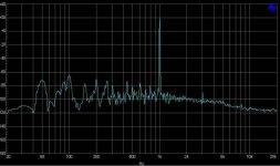
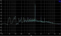
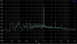
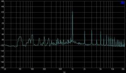
The result is actually quite impressive for such an old design. I didn't bother taking too many measurements (IMD, crosstalk, cosine burst etc), but rather just 4 FFT's with 1kHz sine inputs: 0.5V and 1Vrms, unloaded and 5ohm loaded. Note that these are honest-to-God measurements, with no weighting filters, low-res sampling to reduce apparent harmonic amplitude or so. FFT resolution is taken as 32768 and the spectra are the average of 16 consecutive measurements.
I'm not going to comment too much on them, people can read into them what they want. What is notable, however, is that the noisefloor is dominated by 50Hz and its harmonics. Considering that this amp has been built as an almost exact replica to a KSA100 (layout and wiring-wise), it shows that the grounding can clearly be improved. I'm sure that Pinkmouse's boards' ground separation together with a star-earth point that's not at the PSU caps' centre (as explained by AndrewT, Self and Leach) would help a lot there. The rest is pretty much as expected, with rising odd-order harmonics as the output power increases. Worst-case THD, with the amp delivering over 50Wrms to the load, is a very respectable 0.06%. For 0.5Vrms input the 50Hz noise dominates the THD+N at 0.012% irrespective of the 5ohm load, and THD @ 1Vrms input unloaded is 0.006% due to the higher fundemental amplitude.
Pierre
I sort of lost track of the thread here a few months ago when I finished my first clone (actually I built it on contract for a friend, my research is in PNPWM class-D), but as he now wants a new version built with Pinkmouse's boards I started reading up on the progress made in the meantime.
Back then I posted some time-domain measurements (see thread #320 for them and details on the amp) from a digital scope and interestingly enough few people seemed to be bothered with it, and preferred to discuss more trival matters.
Well, I've since increased C105/106 from 22pF to 47pF on the same amp and took some measurements with an Audio Precision SYS2722. For those not familiar with it, suffice to say it's considered the audio measurement benchmark by many and its features is only matched by it's cost. I've toyed with RightMark AA software with a Creative Audigy4 Pro soundcard but it's not nearly in the same league.
The result is actually quite impressive for such an old design. I didn't bother taking too many measurements (IMD, crosstalk, cosine burst etc), but rather just 4 FFT's with 1kHz sine inputs: 0.5V and 1Vrms, unloaded and 5ohm loaded. Note that these are honest-to-God measurements, with no weighting filters, low-res sampling to reduce apparent harmonic amplitude or so. FFT resolution is taken as 32768 and the spectra are the average of 16 consecutive measurements.
I'm not going to comment too much on them, people can read into them what they want. What is notable, however, is that the noisefloor is dominated by 50Hz and its harmonics. Considering that this amp has been built as an almost exact replica to a KSA100 (layout and wiring-wise), it shows that the grounding can clearly be improved. I'm sure that Pinkmouse's boards' ground separation together with a star-earth point that's not at the PSU caps' centre (as explained by AndrewT, Self and Leach) would help a lot there. The rest is pretty much as expected, with rising odd-order harmonics as the output power increases. Worst-case THD, with the amp delivering over 50Wrms to the load, is a very respectable 0.06%. For 0.5Vrms input the 50Hz noise dominates the THD+N at 0.012% irrespective of the 5ohm load, and THD @ 1Vrms input unloaded is 0.006% due to the higher fundemental amplitude.
Pierre
Attachments

Interesting work Pierre.
So these tests were conducted with the first GB boards, or were they ones of your own design? I would be very interested in seeing the results of testing on my board, not that I want to take any credit, but it would be nice to see if all the good advice and layout after layout worked.
If I had access to an AP rig, I think all the guys would still be waiting for me to finalise the PCB! 😉
Hi Pwatts,
why was it necessary to increase C105 from 22pF to 47pF?
Were there listening symptoms or artefacts found in measurements/testing?
why was it necessary to increase C105 from 22pF to 47pF?
Were there listening symptoms or artefacts found in measurements/testing?
AndrewT said:Hi Pwatts,
why was it necessary to increase C105 from 22pF to 47pF?
Were there listening symptoms or artefacts found in measurements/testing?
And following on, what output devices did you use?
- Home
- Amplifiers
- Solid State
- Krell KSA 50 PCB