I am pretty sure r126 is for bias.. What's r131?😕 I can't find a good reference to it...
Thanks
Thanks
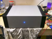
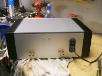
Amp looks great!
MP:
I think that wood looks real nice on the front!!!
Mine still looks like it was breadboarded, but I have been playing it everyday for near six months, and it works and sounds great!
KmJ, I just emailed you. Tell me the damage in an email, and I'll send the funds pronto!
Lyndon
MP:
I think that wood looks real nice on the front!!!
Mine still looks like it was breadboarded, but I have been playing it everyday for near six months, and it works and sounds great!
KmJ, I just emailed you. Tell me the damage in an email, and I'll send the funds pronto!
Lyndon
I just send an Email with the final number to Anders (the manufacturer) and will post and/or Email everyone later. Or, I'll post prices and email about specifict, just so that everyone notices that something is up and checks their spamfilters 😉 .
Mpmarino, lovely amp you've got there 
r126 is for adjusting bias, r105 is for offset according to the silk of Pinkmouses boards. I attached the silk i'm looking at to be sure we're talking about the same thing.
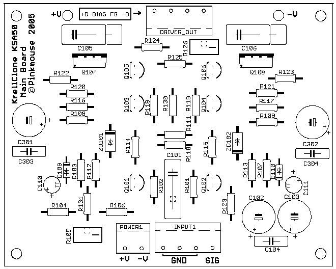
r131 is 22k resistor running from bases of q101 and q102 to the wiper of r105 (offset-trimmer).
In the Wiki there's a description to adjust your bias and offset.
As described in the Wiki,i fired up my mainboard separately from the outputs to check it was working properly.Better safe than sorry..
WIKI
Hope this helps,
Klaas
r126 is for adjusting bias, r105 is for offset according to the silk of Pinkmouses boards. I attached the silk i'm looking at to be sure we're talking about the same thing.
r131 is 22k resistor running from bases of q101 and q102 to the wiper of r105 (offset-trimmer).
In the Wiki there's a description to adjust your bias and offset.
As described in the Wiki,i fired up my mainboard separately from the outputs to check it was working properly.Better safe than sorry..
WIKI
Hope this helps,
Klaas

Nice work MP, a very elegant case.
KMJ, please post here, I still can't find your mail.
All, every time I look at that layout now I see something I would have done differently with a year's extra experience. 😉
KMJ, please post here, I still can't find your mail.
All, every time I look at that layout now I see something I would have done differently with a year's extra experience. 😉
Glad i could help, Mpmarino. If you have questions dont hesitate to ask. Just take your time to check things and adjust bias and offset. Hopefully you'll find out soon that your amp sounds as good as it looks 🙂
Mine sounds better than it looks, still in "al dente"-mode - right now thinking about using regulated PS for mainboard.
with kind regards,
Klaas
edit:Loek, i agree. Al, can you share your thoughts on possible improvements ? layout or topology ?
Mine sounds better than it looks, still in "al dente"-mode - right now thinking about using regulated PS for mainboard.
with kind regards,
Klaas
edit:Loek, i agree. Al, can you share your thoughts on possible improvements ? layout or topology ?
Re: I would have done differently
Thanks for the compliment, but I wouldn't quite go that far!
It's little things, tweaking tracks to get shorter signal paths and more clearance, shifting the odd component to get a neater layout, and tidying up the silk layer. Nothing that would make a huge difference to performance, but they nag at me, you know? 🙂
loek said:So teach us.
Thanks for the compliment, but I wouldn't quite go that far!
It's little things, tweaking tracks to get shorter signal paths and more clearance, shifting the odd component to get a neater layout, and tidying up the silk layer. Nothing that would make a huge difference to performance, but they nag at me, you know? 🙂
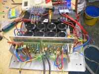
Excellent work, a very clean design. However, if you haven't bolted it up and put it in your system yet, I would suggest twisting all your power runs. But if you want to ignore me, and just listen to it, I wouldn't blame you. 😉
That sounds like the kind of excuse I'd use when I cut a panel wrong, though I'm sure yours was designed that way! 🙂
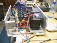
the back has a slit for venting.
That sounds like the kind of excuse I'd use when I cut a panel wrong, though I'm sure yours was designed that way! 🙂
Hi Pinkmouse,
thanks for the kind words.
I know your so right about my wiring, but you wouldnt believe how tight this all is. I might one day but its time to listen to it again🙂
BTW I worked as a test technician along time ago at Perreaux sound. It was amazing what the distortion levels did when I moved the power leads near signals etc.
seeya Arthur
Nice looking amp, Luke ! Good to see those ksa-clones getting finished.
pinkmouse:i understand your thoughts about the pcb, i'm kind of a layout-freak myself. It's like there's always room for improvement, the longer you look at it. That's why it always takes me forever to finish an amp
With kind regards,
Klaas
pinkmouse:i understand your thoughts about the pcb, i'm kind of a layout-freak myself. It's like there's always room for improvement, the longer you look at it. That's why it always takes me forever to finish an amp
With kind regards,
Klaas
I do have a quick question. On my way out the door this morning I took a look at DC offset. With both pots at min (full counter-clockwise). I found about 100mv. I took the bias back a little and 1 side was 'zero-able' but only at a bit above the pot's min. Now, I'm thinking there must be a resistor in series with the offset pot (haven't had the time to look at the schem yet...r131 maybe 😉 ) What if I reduced r131 to 15-20k (from 22k) to center the pot's action a bit?
FYI: my rails are ~+-41.5v if that makes a diff...
A few more tweeks before I give a listen, gotta wire up the XLR connectors. Why XLR you ask? Because they're macho, of course 😀
Thanks
edit: I like it Luke😉
FYI: my rails are ~+-41.5v if that makes a diff...
A few more tweeks before I give a listen, gotta wire up the XLR connectors. Why XLR you ask? Because they're macho, of course 😀
Thanks
edit: I like it Luke😉
I didn't notice that during my testing, but I used a 20K trimmer for offset. How much bias are you running, and are the inputs shorted to ground?
Mpmarino, i dont think changing r131 is a good idea, but thats just a quick uneducated guess. I use 5k trimmer and offset was adjustable to zero, with almost no change when changing bias.
I'd proceed as pinkmouse suggested, i'm sure people like Pinkmouse who are more educated than me can help you sort this out.I dont have a lot of experience with things going wrong .Guess i was lucky .
with kind regards,
Klaas
I'd proceed as pinkmouse suggested, i'm sure people like Pinkmouse who are more educated than me can help you sort this out.I dont have a lot of experience with things going wrong
.Guess i was lucky .with kind regards,
Klaas
pinkmouse said:I didn't notice that during my testing, but I used a 20K trimmer for offset. How much bias are you running, and are the inputs shorted to ground?
I've tried different bias levels but..oops... forgot to short the inputs!
- Home
- Amplifiers
- Solid State
- Krell KSA 50 PCB