I find cooked spaghetti works best, but you have to spray it with five nines purified water every now and again, otherwise the sound really goes downhill.
😉
😉
Thanks for the tip, but, how to solder? Should I use a flour and water (maybe egg) mixture, or perhaps some cake icing?
Are there any errata on your boards I may have missed - before I go too far?
Are there any errata on your boards I may have missed - before I go too far?
Nope, as far as I am aware, if you are using the BOM components, just solder away. The only issue you might have is if you have substituted any trannies, if so, you'll need to check the pinouts.
However, before you snap the boards apart , you might want to work out your mechanical layout, just in case you want to leave any together.
However, before you snap the boards apart , you might want to work out your mechanical layout, just in case you want to leave any together.
Hi Mp,
is that three ground references coming off the alloy common plate on the smoothing caps?
And provision for three more.
I recommend you set up a star ground somewhere local to your PCBs and take one connection from star ground back to the PSU common.
I do not recommend you use the PSU common as your star ground and certainly not by taking separate connections from various points around it.
I agree completely with you. However I have found that in practice about 50% the time for me I have had to make adjustments in the grounding scheme. I am leaving 'taps' all over the place to make it easier and neater to play later. Somehow I get it worked out in the end. Thanks for taking a look!
I do not recommend you use the PSU common as your star ground
How come? I always locate my star ground on a copper plate in the exact center of the caps with excellent results, not unlike many high end manufacturers do. Please explain Andrew... Thanks!
Mark
A lot of people feel that that is a noisy place to put a star I think. This may be true but ...geez...I don't think there is a 'right' way to do it! The right way is the way that works I think.
I hope its pre-sifted flour for the spagetti. Anything less and the electron flow will be degraded.
I hope its pre-sifted flour for the spagetti.
Like Emeril Lagasse says "ya always gotta sift the flower".......
Mark A. Gulbrandsen said:
Like Emeril Lagasse says "ya always gotta sift the flower".......
Followed with a "BAM!" And hopefully this one is not a capacitor exploding..
 😀
😀Hi Mark,
you must have missed all my previous postings both on this thread and many others.
The biggest problem is trying to isolate the pulse charging currents going from rectifier to smoothing caps from modulating the ground reference that all the audio circuits need for a quiet (with zero signal and with signal present) output.
I have found that keeping the rectifier /smoothing caps charging circuit very compact, confines the very large pulse currents and their electromagnetic influence to just that circuit. A separate central star ground tied back to the PSU common prevents the charging pulses from travelling through the star ground.
Similarly, keeping the very high currents from the amplifier separate from the high impedance/input circuits also helps with maintaining a low modulation level on the audio ground.
This part can easily be maintained by keeping the speaker return, Thiel/Zobel network, decoupling returns etc all on a power ground. The low level grounds from the input RCAs, the input RF filter, the LTP CCS ground ref, any decoupled Zener stabilised ref, NFB ground ref, and possibly cascode ground ref should also be on a clean ground.
Finally connect the power ground and clean ground together with a link to the PSU common and a disconnecting network to the chassis (safety) ground.
Have a look at Leach and Self. They draw out a ground schematic that initailly looks different but effectively are the same message as each other.
i like my spaghetti "al dente":
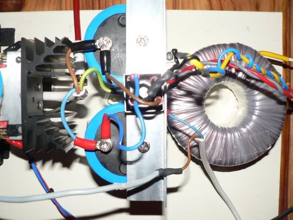
still amp without a case but i like my amp working before i decide on the case-dimensions.
gnd is connected at the bolt which holds the bridge-rectifier .yellow-green wire is connection from psu-gnd to main pcb-gnd (Jan's board). input-signal gnd connects to main pcb-gnd at the same point.
output-stage:
biased for 35 watts class-a, 2x 80mm papst running full-throttle.
i know the psu-rail connections running "through " the main pcb is lazy wiring but it works for now
Klaas
Nice!
Good stuff Klaas, keep it coming!
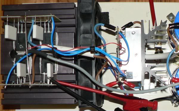
Kind of a big heat sink for the drivers but I'm not one to complain about that!
Nice papst fans, enjoy them, they are expensive here in USA. I think that you will find your output heatsinks are kind of tiny, they will work fine for 30W class A but will get surprisingly hot for .... say 50W class A. Just my opinion based on my amp which runs hotter than a firecracker.
Good stuff Klaas, keep it coming!
Kind of a big heat sink for the drivers but I'm not one to complain about that!
Nice papst fans, enjoy them, they are expensive here in USA. I think that you will find your output heatsinks are kind of tiny, they will work fine for 30W class A but will get surprisingly hot for .... say 50W class A. Just my opinion based on my amp which runs hotter than a firecracker.
Thanks for your kind reply 🙂
I only use these heatsinks for testing-purposes, allready have heatsinks more than twice the size😎
plan to use 3 pairs of outputs on these, biasing for 50 watts class-a.
BTW, these run just "comfortably warm"( guess +/- 45-50 degrees celcius). i always apply rule of thumb with heatsinks: if its hot to the touch, its too hot.
edit: i paid about $60 for 4 of those fans; they're not exactly cheap here either
with kind regards,
Klaas
nice!
Klaas, that is good to hear. By the way, I forgot to compliment you on the exellent construction technique. Unlike me, you appear to have logically connected everything.
$15 each for the fans? I hardly feel sorry for you. But keep up the nice job.
Klaas, that is good to hear. By the way, I forgot to compliment you on the exellent construction technique. Unlike me, you appear to have logically connected everything.
$15 each for the fans? I hardly feel sorry for you. But keep up the nice job.
thanks, in my opinion any working amp is a good one !Unlike me, you appear to have logically connected everything.
i like to work "bottom up" instead of "top down".(i hope this makes sense)
Keep it simple at first. do i need inrush current-limiting ? not overhere if i use 300va toroids. output speaker-relays ? it doesnt produce a thump at startup.
helps to keep things nice and tidy.
with kind regards,
Klaas
Klaas
I like the 3 core power cord
I hope it's not OFC
Must admit spare power cords don't last long at my place.
they get chopped very quickly, very useful hook-up wire.
allan
I like the 3 core power cord
I hope it's not OFC
Must admit spare power cords don't last long at my place.
they get chopped very quickly, very useful hook-up wire.
allan
3-core power cord.. dont think its OFC (i dont know and dont care )
whats a "spare power cord" ? i sometimes see them at other people's houses but not overhere 😀
little off-topic: watching/listening to Fleetwood Mac- The Dance . this amp
with kind regards,
Klaas
)whats a "spare power cord" ? i sometimes see them at other people's houses but not overhere 😀
little off-topic: watching/listening to Fleetwood Mac- The Dance . this amp
with kind regards,
Klaas
home brew
Nothing like listening to the amp that you made.......the bass from these krells is simply amazing. Then again, your own work, if working, is hardly going to sound bad.....
......except when you find yourself watching the smoke rise from some Pass Amp that you were not talented enough to complete (in a year) correctly............

Makes you want to give up DIY permanently...and not read here ever again...and throw away your tools.....but then after a few months of isolation you recall that chipamps are pretty easy......and sound ok......
Nothing like listening to the amp that you made.......the bass from these krells is simply amazing. Then again, your own work, if working, is hardly going to sound bad.....
......except when you find yourself watching the smoke rise from some Pass Amp that you were not talented enough to complete (in a year) correctly............
Makes you want to give up DIY permanently...and not read here ever again...and throw away your tools.....but then after a few months of isolation you recall that chipamps are pretty easy......and sound ok......
Ouch, i know how it feels when a diy-amp goes up in smoke....reminds me to NOT EVER use silicon insulation-pads together with to220-devices again.i tend to torque things rather tight and the sharp corners can cut through the pad. once took me months to find that one out...
driver-pcb prior to testing - thanks Troy for the parts and Jan for the pcb 🙂
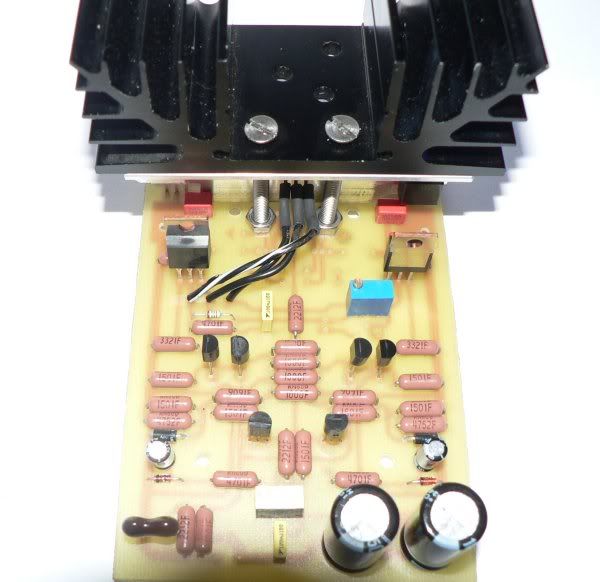
with kind regards,
Klaas
driver-pcb prior to testing - thanks Troy for the parts and Jan for the pcb 🙂
with kind regards,
Klaas
- Home
- Amplifiers
- Solid State
- Krell KSA 50 PCB