Hi,
Krell might know something about building beefy amps and they know plenty about mislabeling capacitors:- 40000MFD must =40000Mega Farads = 40Giga Farads.
My goodness, they can build them small.
I presume we all know they meant 40mF=40000uF with or without the extra "D".
Krell might know something about building beefy amps and they know plenty about mislabeling capacitors:- 40000MFD must =40000Mega Farads = 40Giga Farads.
My goodness, they can build them small.
I presume we all know they meant 40mF=40000uF with or without the extra "D".
Mark A. Gulbrandsen said:And now at post 6300 I throw a monkey wrench into the gear train!
I suppose you mean TO202, not TO220.
There's only a handfull of devices in TO202 clothing from the 80s i can think of. Like MPSU31 from Motorola or the NA32 range from National Semiconductor.
Do you remember the pictures Klaas/kvholio posted of his KSA50 ?
Same board layout but doubled A968/C2238 in the Vas, instead of those TO202 devices.
www.diyaudio.com/forums/showthread.php?postid=840116#post840116
www.diyaudio.com/forums/showthread.php?postid=839051#post839051
Looks to me like Dan d'A made small device changes during production without bringing out a new model version.
Al's version has a new board layout, different Vas, upgraded devices in the driver and output section. And we're running this one full bias. MKIII, the final version ! (but i still say this one should have regulated front end rails)
Att. Mark G.
Sorry to post this in the thread, but I have emailed you a couple of times without reply over the last weeks - are you using another mailaddres than the one listed here on the forum ??
Cheers !
Buhl
Sorry to post this in the thread, but I have emailed you a couple of times without reply over the last weeks - are you using another mailaddres than the one listed here on the forum ??
Cheers !
Buhl
jacco vermeulen said:MKIII, the final version ! (but i still say this one should have regulated front end rails)
Well Jacco, the option is there on the PCB! I look forward to seeing your results! 😉
And now at post 6300 I throw a monkey wrench into the gear train!
Yeah, thats my board, as Jacco already mentioned, just with different transistors in VAS-stage...
I guess this means i'm building mkII-clone mk-I (Jan's boards).
Seems to me Dan made a point of thermal redesign of old board (which used flimsy heatsinks for driver-stage).
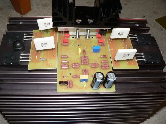
Remember this one ?
My mkIIclone-mkI will look something like this:
With kind regards,
Klaas
that's a nice big heatsink, what is it?
Looking at the pics of your Krell, I notice it has the dark anodized frontplate, if I remember correctly this was only availalbe on the MkII versions (but i could be wrong, been a decade and a half since i was in the business of selling thos).
Looking at the pics of your Krell, I notice it has the dark anodized frontplate, if I remember correctly this was only availalbe on the MkII versions (but i could be wrong, been a decade and a half since i was in the business of selling thos).
(but i still say this one should have regulated front end rails)
No One's stopping you!
NO, never saw those pics! Perhaps Dan was after better thermal stability although the present version is certainly very stable. The JAN and Pinkmouse versions are the same except for the Japaneese semis and lack of current limiting. My pinky boards have the 2SC/2SA semis in them.
I have emailed you a couple of times without reply over the last weeks
I don't remember getting any e-mail. Send me a private one through this site and see if that works.
Mark
Konst, thats heat-tunnel made up of two heatsinks (posted pic before that shows arrangement).My ksa50 doesnt say mkII on the badge, has blue anodized front-panel.The pic i posted from "old" ksa-50 is posted in this thread earlier (MUCH earlier).
With kind regards,
Klaas
With kind regards,
Klaas
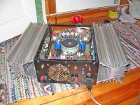
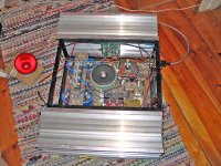
Thought I post some pictures on my slow progress of my KSA50 amp,note,that the wires are not soldered on the pictures so it looks
kind of messy .I seem to have this habit of starting new(other projects)while building one,so this might take some time.😎
But, it aint no need to hurry.😉
You can see the red 100w in the background.😀
kind of messy
.I seem to have this habit of starting new(other projects)while building one,so this might take some time.😎 But, it aint no need to hurry.😉
You can see the red 100w in the background.😀
Attachments
oh, one thing.
If you afraid of turning the powercord the wrong way and switching phase, is it possible to put a thermistor on both the hot and neutral powerpin?
I would say no but want to be sure.
If you afraid of turning the powercord the wrong way and switching phase, is it possible to put a thermistor on both the hot and neutral powerpin?
I would say no but want to be sure.
In essence you are reducing the Mains impedance to your amplifier..
Make sure you factor the voltage drop caused by the additional current limiter... seems a little redundant though.
Make sure you factor the voltage drop caused by the additional current limiter... seems a little redundant though.
Damn, someone already answered...
I was a bit confused when I wrote that.
Anyway, I was afraid that turning the plug the wrong way would render the thermitor useless but it doesn't matter which side I place it since the overall impedance of the primary winding is raised no matter what. Heck, I don't even use one, I have a softstart
Let's just say that it has been one of those days
information
...i'm sorry....i'm a new start member...i would like to realize this amplifier but strickly following the original ksa50's specifications and compponents and lay out and board place inside the cabinet.
i've seen that kvholio did a grat job....i would like so much to have some support from him...for instance let me know the measurements of the amplifier...where i got the components if i could know the disposition of the board inside the amply....or...the correct schematics and layout.... or.....if anyone that has already made this amplifier ....could give me any support.....i would apprechiate veery much.
I'm really lookin forward to receive some support from this good commuity.
Stefano.
Hi Stefano, first of all welcome to this forum.The ksa-50 to clone is mk-II, my original is mk-I, so i dont think measurements of mk-I will help you a lot.I'm in the process of cloning mk-II but this is slow progress.There are two pcb-layouts you can use, first are Jan's boards (these are the ones i use). If i'm not mestaking Rabstg (Troy) can offer them-pls correct me if i'm wrong.
Second are Pinkmouse boards, these are more flexible in heatsinking drivers and have overall more flexible layout and nice groundingscheme.Mark A. Gulbrandsen offers those. I dont know about availability of parts-kits right now, but im sure someone here can tell you.
For a lot of information i suggest the wiki:
http://www.diyaudio.com/wiki/index.php?page=Building+guide
btw, i dont think there's anything wrong with a little "diversion" from the original, for instance using 3 pairs of output-transistors instead of two pairs, to increase your safety-margin.
Hope this helps you further Stefano, if you have questions you will find your fellow-members here most helpfull
With kind regards,
Klaas
Hi,
the change to 3pairs is more to do with using plastic packaged output devices than increasing safety margins.
eg. the 2pairs of MJ15003/4 have a combined spec of 40A and 1000W and crucially Tj max=200degC.
3pairs of To247/264 can be 45A, 900W to 1200W but Tjmax=150degC.
Taking all these factors together the convenience of plastic package and increasing to 3pairs gives similar electrical performance. I do consider 3pairs of 150W devices to be a bit light and would tend towards 4pair of 150W devices.
sorry Mr. Kvholio..some questions.....
you implemented the first mkI.......is working
...have you ever compared with the orignal krell?
....i would like to have the original project.....because that's what 'm tryng to clone.........because i think that modifying something.... it would sound really different....(just modifying the lay out ... or...the disposition inside the case).....and so we wouldn't obtain that krell's sound!
Your realization since turned out great....but... did you use the original dimension of the krell's ksa50 board and case and the metal cool ( don't knw hte english word for the cooler) ?!
Does anyone has the original's board lay out?...pictures of the inside of the original krell....
i'm sure that i'm not so much clear ...that's why i'm going off without fond a starting point!
....this 3d is really long...and there are so many ideas...that's why i'm confused!!
i would like to realize by my self the pcb board.....and not buy from someone else...because i would like to built the board with some specific characteristics......like gold plated...high density...etc.....
please....could you give me some suppoet?
you implemented the first mkI.......is working
Let me first clear up some misunderstanding:i own original mk-I, i didnt clone it (no need to clone what you own 😉 ).
From what i heard from people on this forum, my ksa-50mk-I is probably retrofitted with pcb from mk-II.
I am attempting to clone a ksa-50 mk-II (which runs on lower psu-voltage than my mk-I).
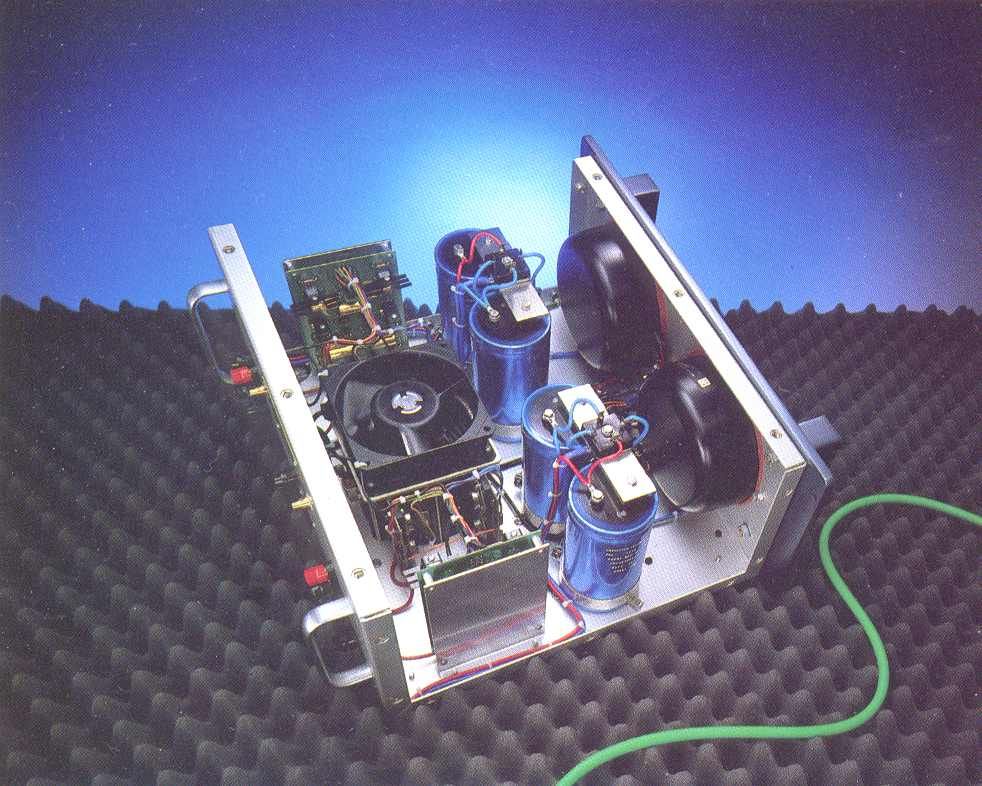
The pictures i posted earlier from inside of amp were pictures of original mk-I, not of clone.
I can help you with layout of powersupply etcetera, also with wiring like original (in my opinion krell did some typical things with wiring).
I dont think its wise for me to give you layout of pcb (dont think Dan-the-man would like it).
If you have particular questions, please let me know.
With kind regards,
Klaas
- Home
- Amplifiers
- Solid State
- Krell KSA 50 PCB