a new one needs some advice
Hi
me Ilike to build the Krell clone
a dump question how to order the pcb?
and which version ??
a bit lost
reading and reading maybe the best thread here😉
It will be not my first project
and me musician not rich at all
not french at all
but how much will it be $$$$wise
Hi
me Ilike to build the Krell clone
a dump question how to order the pcb?
and which version ??
a bit lost
reading and reading maybe the best thread here😉
It will be not my first project
and me musician not rich at all
not french at all
but how much will it be $$$$wise
Re: a new one needs some advice
pcbs
ask Mark Guldbrandsen
this is last version
régine's said:Hi
me Ilike to build the Krell clone
a dump question how to order the pcb?
and which version ??
a bit lost
reading and reading maybe the best thread here😉
It will be not my first project
and me musician not rich at all
not french at all
but how much will it be $$$$wise
pcbs
ask Mark Guldbrandsen
this is last version
i noticed in the Krell-O-Tracker that different Klones have different numbers of output devices. is this just a matter of slapping in some more in the right spots, or does the circuitry require revision to match? it'd be nice to get a little bit over the original 50 watts, or at least run each transistor a little cooler.
Hi,
the KSA50mk2 was specified at 50W ClassA using 2pairs of 250W 20A output devices (MJ15003/4). Total /side = 500W & 40A
The later Klone PCBs are using 3pairs of plastic packaged output devices that can vary from 130W to 230W each generally rated at 15A or 16A. If you go towards the lower power end I would recommend more than 3pairs. I am planning on using 5Pairs or 6pairs of 150W 15A devices and by using large passive heatsinks have a margin to push the spec higher (30Vac rather than 28Vac)
without overstressing the output stage.
If you add more output boards you can add as many devices as you think fit. However you do need to look back through the stages to ensure you maintain some semblance of balance in the specification. Copy the standard Klone if that suits your skill level or start to modify it if that is the direction you feel able to cope with. It's DIYaudio here.
maybe i'll just stick to the original output section...i wanted to spend some time adding non-sound related bells and whistles to mine like a pair of VU meters, headphone outputs, some decorative lighting and some other stuff...i have to assume they will come with their own implementation problems so i'll go with a known working output stage configuration.
on the PSU side, i've always been interested in capacitance multipliers, has anyone considered using one like this in a klone? http://sound.westhost.com/project15.htm
might help to make the whole thing a lot more compact.
on the PSU side, i've always been interested in capacitance multipliers, has anyone considered using one like this in a klone? http://sound.westhost.com/project15.htm
might help to make the whole thing a lot more compact.
Hi to everybody......
.....i'm wondering if there is anyone with the originl krell ksa50 first version.....
....if yes.....
what do oyu think about thi krell?...are you happy with it?..or would you change it?
i'm curios to know....where do you match it...and what do you think it can dive a the best....wich type of loudspeaker!?
Stefano.
just a question.....anyone knows why the original krell has the heatsink on the side....if the output devices are cooled on an hearsink inside of the amplifier and with a fan cooler?
let's look at the picture attached...(this is the ksa 100 )
...anyone can tell me what that side heatsink needs for?
let's look at the picture attached...(this is the ksa 100 )
...anyone can tell me what that side heatsink needs for?
Attachments
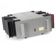
Simple, that is a later model, from when Krell had more money to spend on case work.
Stefanoo, all this information is already in this thread, you just need to do some reading.
Stefanoo, all this information is already in this thread, you just need to do some reading.
Hi,
different versions of the amplifiers.
As far as I know the fan cooled versions were the earlier models.
Krell appeared to move to the massive looking passive sinks in the later models.
Why? I can guess at:- less noise, less dust, more reliability, more aesthetic value.
different versions of the amplifiers.
As far as I know the fan cooled versions were the earlier models.
Krell appeared to move to the massive looking passive sinks in the later models.
Why? I can guess at:- less noise, less dust, more reliability, more aesthetic value.
Stefanoo said:just a question.....anyone knows why the original krell has the heatsink on the side....if the output devices are cooled on an hearsink inside of the amplifier and with a fan cooler?
let's look at the picture attached...(this is the ksa 100 )
...anyone can tell me what that side heatsink needs for?
if that had internal fan heatsink?
where's the vent on the top cover?
allan
I have figured why that model has the heatsink on the sie...it's because it' not the ksa 50 but the ksa 100!
i'm going to buld a ksa 50 but with passive cool (heatsink on the side!...i think it's more silent and better look!)...but based on the original electrical schematic.
...here the deal.....
i just found two schematics that are both referred at the same krell ksa 50...but the value of the components and the circuit is different....so i don't understand wich is right...
I would be interested to built the mkI (the first version and not the mk II ...because i read that is better the first version than the last!)
..one of the schematics is that one at the firs page of this 3d..and the other one is attached here...(it's from that link of the ksa 100 mkII )
this last one seems to be the first version.
Could anyone help me to find out the right electrical schematic of the krell ksa 50 mkI ?
best regards,
Stefano.
Attachments
Stefano,
That link is to the older version... not the Mk-2 version. I always refer everyone to Jan's site for the Mk-2 schematic as its the closest to what the original Mk-2's were. If you can get them use the 2SC/2SA Japaneese devices as they DO sound better. They will fit the Pinkmouse board if you bend the leads the right way. On Jan's list and diagram just omit the protection scheme since none of the KRell's had that. I always use this list. Why anyone would want to deviate form the original is beyond me when all of the parts are pretty easy to source. It takes too much time and energy to build one... might as well do it right!
Jan's Parts List
Jan's Schematic
Good luck on yours!
Mark
Mark, Does the 2s/2240/970 combo result in better bench performance on the Pink version?
Running squarewaves with the Mpsa 42/92 combo, I see the beginnings of the rounded trailing edge beginning around 15khz. 1 and 10khz are perfect. No oscillation's at any frequency. .22 cap test shows controlled slight ringing of the start of the top wave as usual
My 150 watt W. Synder version of the Krell (uses the 2240/970) shows perfect squarewave performance out to the 50 khz limit of my Spectral dynamics sd-104a generator.
The toshiba's are speced as 100mhz verses 50 for the Mpsa 42/92 I believe.
I haven't yet placed them in my system, just running them in the garage for now.
welcome any comments
David
No, have not made any measurements except by ear. I have alot of test equipment here but over the last two years have relied on it les and less.... anymoer I only take an amp to the bench if there is an obvious audible problem... then I want to see whats up.
I have listened to both sets of semiconductors extensively having now built three KSA-50's. One used the MPS type and the other two used the Japaneese devices. The two equipped with the 2SC/2SA devices had a little bit better refined and smoother high end. The advantages of using the Japaneese devices are obvious just from looking at and comparing their spec sheets! Dan switched to them in all his equipment that used small signal devices for definate reasons! It wasn't cost.
Mark
Are you using the GR or BL versions of the Toshiba's and did you match for current gain?
In my Class A design manual from Synder, he reccomended the higher HFE versions of this tranny in his circuit.
just wondering if you remember what you used.
My next 3 versions will be 1 center channel and 2 air cooled versions with different outputs and said Toshiba's for the halibit
Variety is the spice of life, is it not? 🙂
David
He calls it smoother, I call it softer! 🙂
It's really down to taste I found, the differences are not great enough in my opinion to recommend one device over the other. Try both if you can get them.
It's really down to taste I found, the differences are not great enough in my opinion to recommend one device over the other. Try both if you can get them.
When I'm certain performance testing has brought out any bugs, I'll do the Pepsi challenge between the Synder 150 watt version and the 50 watter
I have Martin Logan SL-3's and perfect older version Quads (42,000 serial #'s) with new tweeter panel's to see what's cooking.
David
I have Martin Logan SL-3's and perfect older version Quads (42,000 serial #'s) with new tweeter panel's to see what's cooking.
David
- Home
- Amplifiers
- Solid State
- Krell KSA 50 PCB