He calls it smoother, I call it softer!
Thats not quite what I said...... And its not all that simple to compare them that way.....
What I di say is this ... "The two equipped with the 2SC/2SA devices had a little bit better refined and smoother high end".
There is a big difference between smoother and softer in my book. I always tend to associate softer with a loss of hf definition.
By better refined I mean with the Japaneese devices the extreme hf was better defined, perhaps because of lower distortion and the net result was a smoother high end or more refined. I don't care why really... what ever device sounds better stays in place!
In reality the high end had a little better resolution... I heard things with the 2SC/2SA devices that I didn't hear with the MPS stuff.
I have never matched any devices going into these amps. Getting OP devices from the same lot has worked pretty well for me for the most part. I measure the voltage across all the emitter resistors in the OP stage of a completed channel and sub in other devices for the ones(only three so far) that are more than 5% off.
I'd have to open up my amp and look at my 2SC/2SA devices to see what designation they have...I am out of them and don't remember off the top of my head. Since I am going to build the KSA-100 MK-2 I will be ordering more of them in a couple of weeks.
Mark
The resistors on the outputstage of the schematic labeled RVI 1-3, where did they go? Are they some optional components or just obsolete?
They are not needed inless you are implemnting current limiting as on Jan's design. The original KSA-50 did not have current limiting except by fuse. They were omitted fomr the Pinkmouse board cause it has no current limiting option.
Mark
Mark
Hi Stefanoo,
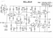
compare the Mk1 (pre '83) to the Mk2.
Note the lack of zeners on the LTP tail currents, addition of the electrolytic capacitor across the LTP emitters, RC in// with predriver Re, omission of the follower to the VAS, cap feedback to inverting LTP, VAS referenced to ground.
Be prepared to change these details to Mk2 spec to at least listen to why Krell changed the schematic.
i would like to built the ORIGINAL MK I ....... NOT the mkII.
I only would be interested on the ORIGINAL MK I project.
i would like to find the electrical schematic for the MK I ...the two that i have now......i don't which one is the MK I ....if there is one correct!
Could anyone help me to find the original and correct electrical schematic and......if would be possible....the lay out of the board?
...for instance...on the link of the ksa100 mk II... there are pictures of the components layout on the board.
by having the correct electrical it wouldn't be that hard to re-built the board.
Anyone knows how can i get a picture of the components lay out of the ksa 50 mk I board?
thanks.
Stefano.
Stephano, they are probably both correct, Dan was prone to changing things. As for photos of the MK1 board, I did a lot of research and didn't find any Krell pics on the web that are not shown or linked to in this thread. If you're really set on building a MK1, then your best bet is to buy one, copy it, then sell it afterwards.
but this is the krell ksa 100.
...i undertand...
in the the pdf file the label says : 1983 .
it seems to be the first one ad most accured one.
the idea to buy one rebuilt and sell...it's nice.....but......i don't know!
it's not so easy to find one used!
....second...youl'll never know...if the unit that you get is modified or not.....if it's the mkI or the mkII........it's a bet like oyu said!!
I would rather prefere to find the electrical and correct electrical schematic and then built the board based on pics that i have.
The lay out would be really close to the lay out of ksa100mkII.
ksa50-1
lloyd has a schematic of the ksa50 series 1 on his website, it is basically the same as the 100 shown, with half the outputs, and lower ltp bias resistors etc...
But there are no board photos
Stuart
lloyd has a schematic of the ksa50 series 1 on his website, it is basically the same as the 100 shown, with half the outputs, and lower ltp bias resistors etc...
But there are no board photos
Stuart
ksa50 schema
Nope, I mean Lloyd Maclean, not sure what the URL of his site is, but he had a good complement of all the early Krell schematics, and one of them is explicitly listed as ksa50 series 1.
I pulled it from the site when he first showed us his stuff, so I haven't checked since, if it is not there anymore email me.
Stuart
close enough...
Hi,
yes, and the schematic I was speaking of is
http://home.ca.inter.net/~lloyd.maclean/Krell/KSA50.pdf
The transistors seemed to change based on availability and better specified parts becoming available over time.
Stuart
Hi,
yes, and the schematic I was speaking of is
http://home.ca.inter.net/~lloyd.maclean/Krell/KSA50.pdf
The transistors seemed to change based on availability and better specified parts becoming available over time.
Stuart
Hi Stefanoo,
that pre '83 KSA50 and the KSA100 just posted seem to be almost the same.
Have you had a chance to compare the schematics yet?
Can you manage to build a PCB that has the traces and component locations of both, possibly including a few jumper pins on board to allow the alternative topologies? Both the mk1 and mk2 can thus be compared and even individual changes compared.
Krell faceplate
At the Salt Lake City Shootout, I loved the pewter faceplate on BillW's
Krell 100. I am sure it was also "cool" to have the black logo plate, but I think it would have looked much better to have had the brass one, with the dark pewter behind it. I wonder if it is still possible for BillW to acquire from Krell a brass plate as well. Of course, he could care less about that type of thing.
I think I am going to anodize both my Aleph 3 and the Krell with that
pewter. Much more interesting than the black...
Style Man Lyndon
The Blue hard coat at Pilkington also looks nice... Perhaps you could hire Desmond Herrington for an amplifier decoration consultation.
Mark
Mark
ThermalTrak(tm) Transistor??
All,
Bias Diode built-in on output Transistor!
Look at the below URL.
http://www.onsemi.com/pub/Collateral/NJL3281D.PDF
http://www.onsemi.com/pub/Collateral/NJL3281D.PDF
http://www.onsemi.com/pub/Collateral/AND8196-D.PDF
Pin out will not work with Al board but would this work for KSA50 Clone and what would we gain?
OnSimi tech sheet specificly mention Class AB amp application but not mention anything about Class A amp.
Benefits (from On-Semi tech sheet):
- Eliminates Thermal Equilibrium Lag Time and Bias Trimming
- Superior Sound Quality Throught Improved Dynamic Temperature Response
- Significant Improved Bias Staility
- Simplified Assembly - Reduced Component Count
- High Reliability
Hi,
the Klone and the original were never designed to use diode control of the bias.
It would require a complete redesign of the driver and output stages and a new PCB. If you look at the example circuit, you will find that the reduced component count comes from removal of the normal bias circuit, but at the expense of much more expensive components.
It would no longer be a Klone.
However the Leach clone does use diodes as it's main temperature compensation. Go ask the question on their threads.
Soft starts:
I bought 2 of the Hypex soft starts (one for my Krell klone).
This morning I found this if anyone wants one but doesn't want to drop the $70 bucks a piece (ouch!).
http://eshop.diyclub.biz/product_info.php?products_id=402
Plain jane soft start for $10.
I have ordered thier remote control volume and can say they are responsive and the product works and is decent.. But hey, it's a $10 item, it's not going to be dipped in gold.
- Home
- Amplifiers
- Solid State
- Krell KSA 50 PCB