Hi,
could someone explain the working of the 470uF caps shown on the pre83 KSA100? post6271, attached to the LTP emitters and VAS emitters.
Seems like extra AC gain?
could someone explain the working of the 470uF caps shown on the pre83 KSA100? post6271, attached to the LTP emitters and VAS emitters.
Seems like extra AC gain?
Crown used something like that on the early DC-300's. I think they called it a "bootstrap capacitor". Anyway, that old design is not the way to a good KSA-100! The MK-2 I believe took care of many of the ailments of the early versions of the amp.
To me the next step for this site although in a seperate thread would be the KSA-100MK-2 since we have the drawings and since its not all that much more complicated than the 50 is. The MK-2 amp can also be built as the KMA-100 which had the addition of a regulated supply for the main board and was a monoblock.
Mark
so ....
any of the krell preamp schematics floating around out there?
any of the PAM series maybe?
mlloyd1
any of the krell preamp schematics floating around out there?
any of the PAM series maybe?
mlloyd1
mlloyd1 said:so ....
any of the krell preamp schematics floating around out there?
any of the PAM series maybe?
mlloyd1
now there's a thought
any views on the preamp?
is it worth cloning or which model?
allan
Krell progressing...
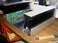
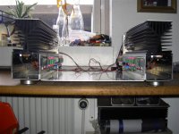
I have now modifyed, my chassis, the 2 duct fans will be controlled separate by NTC resistors, and the fans at the heatsinks will be controlled together by 1 NTC.
Idle speed will be about 4 v and max speed at 10,5 v
Still a long way to go.
I have now modifyed, my chassis, the 2 duct fans will be controlled separate by NTC resistors, and the fans at the heatsinks will be controlled together by 1 NTC.
Idle speed will be about 4 v and max speed at 10,5 v
Still a long way to go.
Attachments

hi ROVSING,
Very impressive so far. Those fans should be at the front so we can see them. 😉
regards
Very impressive so far. Those fans should be at the front so we can see them. 😉
regards
Hi Rovsing,
The hot end of your sinks should have the output devices farther apart compared to the cooler end. Which way are the fans blowing/sucking? Moving the hot end ones towards the centre nearly achieves the same thing.
BTW, I would put the fans on the outside so we can see them clapping😉
The sinks you are using have fin spacing to suit natural drafting, so they won't dissipate quite as much heat as close finned sinks designed for fan cooling but they look plenty big enough. What is the Pd you are planning on using?
Thank you greg
They will be at the front partly visible, and maybe with a pale blue light shining at them.
They will be at the front partly visible, and maybe with a pale blue light shining at them.
Hei Andrew
The fans are blowing through the duct, if you look at the new picture that i have attached, you can see that the heatsink got a Y shape, that's why i have put those plates at the top(haven't fastened them yet) to make a triangular duct for the upper fans.
If this construction can't keep the heat away, i will trow this thing out !😀 It has already got much bigger than first planned.
D=400 mm H=175 mm W=475 mm
Attachments

Actually they were on the way to the junkyard from where i work got 4 of them, i like recycling especially if it's something that i can use !😀
I don't know their data, but they should be able to do this job in kombination with the fans.
I don't know their data, but they should be able to do this job in kombination with the fans.
ROVSING said:hi Konst
If you got a good eye fore it i'm sure you could make a good income collecting garbage !
Amazing what people trows out nowadays.
Here's a picture of the NTC's mounted in the opposite end of the fans.
Once it's running you can get rid of the heater under the table😀
put on some red and yellow leds, a bit of clear loose plastic flapping
in the fan exits, wood on top.
tell the wife it's and artificial wood fire heater

thought i would beat Upupa
seriously,
nice work😀
allan
ps i really do feel imspired to finish of mine.
Good idea, my wife allways wanted a fireplace !😀
But now it's nearly summer here 16 degrees celsius !
Ill bet you can beat that in Sidney !😉
But now it's nearly summer here 16 degrees celsius !
Ill bet you can beat that in Sidney !😉
ROVSING said:Good idea, my wife allways wanted a fireplace !😀
But now it's nearly summer here 16 degrees celsius !
Ill bet you can beat that in Sidney !😉
summer over here
Its starting to get cold

http://weather.ninemsn.com.au/weather/national/nsw.asp?location=sydney
allan
Very slick metalwork ROVSING. You obviously have better metalworking-skills than me.
btw, heatsinks im using are also salvage parts from electromotor-softstarter at my work. when i saw them i knew they were mine 😉
Keep up the good work !
with kind regards,
Klaas
btw, heatsinks im using are also salvage parts from electromotor-softstarter at my work. when i saw them i knew they were mine 😉
Keep up the good work !
with kind regards,
Klaas
RONSING do you have a schema of it?🙄the 2 duct fans will be controlled separate by NTC resistors, and the fans at the heatsinks will be controlled together by 1 NTC.
summer over here
Its starting to get cold
Getting warmer here after the looong cooold winter.😎 😉
Yes, I would like to see how it worls as well. I am about to build a permanent fan cooler into my 99% finished KSA-50. Actually the fan controller is the last touch.
Thanks!
Mark
Thanks!
Mark
- Home
- Amplifiers
- Solid State
- Krell KSA 50 PCB