Hi mate, sorry to hear you've been ill, I hope you're now well on the way to recovery.
I was waiting to see pics of the output stage, just to make sure the mods I made to the board for you personally worked.
I like those pink ceramic stand offs! 😉
I was waiting to see pics of the output stage, just to make sure the mods I made to the board for you personally worked.
I like those pink ceramic stand offs! 😉
Thought you might, Al.
Pink adds somewhat of an authentic look, n'est ce pas ?
I look great as well with a sleeve around my neck.
It's thick wall teflon tubing, cut to uni-size pieces.
I spotted that IKEA sells 1/2 gallon containers with Hama(or Halma?) beads of a simular size in a range of colors for a few GBP. It is not PTFE, but HDPE, shouldn't matter that much for sleeving component legs.
Attachments

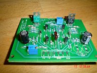
A picture of one of 6 main boards.
All matched Toshiba devices, all resistors also matched within 0.1% accuracy, Roederstein caps and Cornell Dubilier silver micas.
No beautifull Dales, but don't let the size fool you.
Missing caps because of voltage regulators and dc-servo.
Not sure yet how i am to squeeze in the original Toshiba devices for Q105/Q106.
Attachments
😉
Oh my God...
We are observing the birth of the first Ksa clone with Pink socks !
I don't know how much these socks are going to increase amp's WAF, but they look eccentric, for sure. 😀
To Mark:
My boards arrived the last week, they look awesome. Thank you very much Mark for the help with this GB.
I want to thank also Pinkmouse for His designing efforts, a truly great PCB, Al.
Thank you again guys.
This amplifier may be something very special, observe the number of hits...people ...
Is very interested.
I tried once the model 100....but had problems....some mistake during construction.... result burned transistors and them i did not insist anymore.
But this thread is turning me excited with this one...as cannot be bad with so many people interested on it.
Beautifull thread.
regards,
Carlos
Upupa Epops said:Is not neccessary to use 0.1 resistors, Jacco....
Pavel, not necessary but fun. Pink socks are not necessary either but are fun too.
Some of the 0.6W resistors on the boards are 2% accurate
low noise types that i have aquired the Dutch way: cheap and lots of them.
I have close to 20.000 resistors and have to check their value anyway.
For the dc-servos i have OP07AZ opamps, a full rail from a skipped active crossover project. Sent some of these to ModEvil in Brazil for upgrading his Brazilian Gradiente amplifier.
The opamps were made by PMI, now AD, the AZ is the military version that has very low temp drift and voltage offset values, and has a low noise number.
With a standard filter on the positive entrance of the opamp, rolling off at 0.25 Hz, equal resistor value from the - entrance to ground . A resistor on the output to limit max output current, and a small cap across output and - entrance.
Not much interesting to say about dc-servos really.
As i have 9vac step-up transformers for regulating the voltage for the rails of the front end, they'll deliver their 9vac to TO220 voltage regulators for the chips.
You are too hot for this hobby, Carlos.

Attachments
I have many resistors too ( maybe more than you ), is nice feeling, to take them and fondle them... I understand to love of Harpagon.... 😀
Figured you would, Pavel, and read Molière.
The only problem lies with the girlfriend:
she wishes me to fondle her, and i want to fondle resistors and antique transistors.
The only problem lies with the girlfriend:
she wishes me to fondle her, and i want to fondle resistors and antique transistors.
Hi Jacco,
are the Tosh To92 bce instead of cbe?
Then try inserting the body at 90 degrees to the normal orientation and bending the legs c to the back e to the front and b to the middle to align with the pin holes and then there is space, no need for insulation. Not as neat but almost workman like.
Did your last comment reveal the real source of the neck problems? Handbags at 5 paces are pretty drastic!
Hi all Parts GB'ers...
Can anyone who is using these kits for Jan's boards send me an email ASAP?
I have all the kits completed, but decided in the intrest of being thorough to actually swap out the transisters according to the end usage.
According to the Wiki, the driver transistors between the two PCB's are different.
http://www.diyaudio.com/wiki/index.php?page=Building+guide
Chapter 2, item 2.
rabstg said:Hi all Parts GB'ers...
Can anyone who is using these kits for Jan's boards send me an email ASAP?
I have all the kits completed, but decided in the intrest of being thorough to actually swap out the transisters according to the end usage.
According to the Wiki, the driver transistors between the two PCB's are different.
http://www.diyaudio.com/wiki/index.php?page=Building+guide
Chapter 2, item 2.
Hey troy, I've made Jens boards using jens parts and I think I know what you are talking about. Email me or post in more detail please. I think still4given (who has made both) also knows of that which you speak. Look at post #2501
destroyer X said:Is very interested.
I tried once the model 100....but had problems....some mistake during construction.... result burned transistors and them i did not insist anymore.
But this thread is turning me excited with this one...as cannot be bad with so many people interested on it.
Beautifull thread.
regards,
Carlos
Carlos, is that really you? in this thread? You must have been impressed because you skipped 99% of this thread, its a little long now.
I thought the drivers are identical ?
Different is using an MJE15032 for the Vbe multiplier instead of a 2SC3955 as suggested by Pavel.
And different is the pinout for the small signal devices, ebc instead of bce. For that i've kept orientation of the devices identical but sleeved the emitter underneith the case to the other side.
Different is using an MJE15032 for the Vbe multiplier instead of a 2SC3955 as suggested by Pavel.
And different is the pinout for the small signal devices, ebc instead of bce. For that i've kept orientation of the devices identical but sleeved the emitter underneith the case to the other side.
Igreen...yes, i have skipped the thread to take care of others, and really
The thread is now very rich.... enormous and has many interesting subjects to read.
regards,
Carlos
The thread is now very rich.... enormous and has many interesting subjects to read.
regards,
Carlos
lgreen said:
Hey troy, I've made Jens boards using jens parts and I think I know what you are talking about. Email me or post in more detail please. I think still4given (who has made both) also knows of that which you speak
�£DELTA AUDIO DENMARK
www.delta-audio.com
Krell-Clone KSA-50 II
Suggested Component List (Last updated 17.03.2005)
Q101, Q103 2SC2240 <-- Here ----------<
Q102, Q104 2SA970 <-- Here ----------<
Q105 MPSA92
Q106 MPSA42
Q107, Q110 MJE15033
Q108, Q109 MJE15032
Q111 2SC3955
KrellClone KSA50 BOM (Al's)
3 MPSA42 Q101, Q103, Q106 T092
3 MPSA92 Q102, Q104, Q105 T092
2 MJE15033 Q107, Q110 T0220
1 MJE15032 Q111 T0220 or MJE15030
2 MJE15032 Q109, Q108 T0220
3 MJW1302 Q501, Q502, Q503 T03P
3 MJW3281 Q504, Q505, Q506
Power supply caps
I’m still not sure if I should use one large cap or many small caps in parallel for the power supply. Both have advantages and disadvantages.
This site (http://www.lcaudio.com/index.php?page=29) describes a different method for using paralleled caps in their Class A 50 Watt amp.
Quote:
“Our novelty Virtual 4 pole Capacitor bank is one example. In this bank 10 high speed low impedance power electrolytic capacitors are connected together to form 2 big caps for the amplifier rails. None of these caps are connected in parallel, as this would pose problems with current transfer woppling. This is when several low impedance caps are connected directly in parallel; they tend to compete for the power. The first cap gets current first, then the next tries to take some of the charge from the first, and so on. In terms of sound performance, you get a loss of precision in the high frequencies and a cold midrange at larger power outputs - where the woppling is more severe. One alternative is to use only large can capacitors. This to some extent also will solve the two problems described, however almost any large can capacitor will work very slowly, and play with a slow and out-of-beat bass. The V4P setup however solves both problems! Bass is fast and in sync, while precision in mid and high ranges are intact at all levels. Due to the special V4P network, power is charged and discharged to each cap at exactly the same time and rate. At the output of the V4P network no electrolytic caps are present, so here we found a perfect opportunity to place a huge Polyprop (22uF) which this way will be the only capacitor the amplifier can 'see' above 1 kHz.”
And
“Current is fed to each capacitor simultaneously through a low-inductive Power Resistor. “
I assume that each cap has a series resistor from the bridge and another one leading off to the power amp?
Is this assumption correct? If yes, what would be the value for the resistors?
lgreen said:Hey troy, I've made Jens boards using jens parts and I think I know what you are talking about. Email me or post in more detail please. I think still4given (who has made both) also knows of that which you speak. Look at post #2501
I think you mean Jan's boards......
I know it is difficult to remember the difference between Jan and Jens
\Jens
- Home
- Amplifiers
- Solid State
- Krell KSA 50 PCB