pinkmouse said:Oh, and what the final fan/softstart pcb will look like. Who needs complicated! 🙂
Pinkmouse-
You are planning to have pcb's made for the fan/soft start circuit, yes? I have made my own boards from Jan's info and have them stuffed and ready to test. Ultimately, I would like to have a fan (if the softstart comes with it that's gravy) as well. If you are having boards made, will they be made available for purchase?
thanks,
SteveA
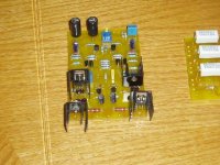
SteveA said:Here is my board ready to go (more or less):
SteveA
Looks nice, good work. I think you will want to use larger heatsinks for those driver transistors (the 2 closest to the edge).
lgreen said:
Looks nice, good work. I think you will want to use larger heatsinks for those driver transistors (the 2 closest to the edge).
I have those sinks too, what if I use 2 and piggy them back to back ... would it be enough?
K-amps said:
I have those sinks too, what if I use 2 and piggy them back to back ... would it be enough?
Possibly. They take a while to get hot so you will have plenty of time to monitor the temperature.
K-amps said:
I have those sinks too, what if I use 2 and piggy them back to back ... would it be enough?
That's what I've done. If you look close each transistor has two heat sinks attached. I'll see if I can attach some larger heatsinks to them.
SteveA
Pinkmouse,
For your soft start circuit, you only used a thermistor? Won't this not help in quick restart scenarios? Did you use it for the simplicity? Can I ask any more questions?
For your soft start circuit, you only used a thermistor? Won't this not help in quick restart scenarios? Did you use it for the simplicity? Can I ask any more questions?
Al, have you for soft start only termistor ? Any bypass relay ? In this case is higher inner resistance of PS, which isn't optimal...
Pavel -You really don't let me get away with anything do you! 😀
Yes it is as simple as it looks, but it works for Pass Labs, so I think it will do for me. And Phil, ask away! 😉
Guys, I wasn't planning to do anything with this PCB manufacturing wise, simply because I designed it to use up some junk box parts I had lying around. If you want this kind of thing, there are a couple of good designs in other threads, so we don't really need another.
pinkmouse said:
Guys, I wasn't planning to do anything with this PCB manufacturing wise, simply because I designed it to use up some junk box parts I had lying around. If you want this kind of thing, there are a couple of good designs in other threads, so we don't really need another.
www.olimex.com are great for one-off pcbs, cheap as chips and a 5 day service from Bulgaria to EU.
Hi all,
what controls the LTP current balance?
If Ir112=Ir116=0.5*Ir111 then the currents in the LTP are balanced. The volts drop across r116 controls the current in q105 emitter and r120. The volts drop across r120 controls the current in q107 emitter and r122.
These volts and currents define the quiescent conditions for the LTP, EF and VAS.
However if the LTP is out of balance then each of the following EF and VAS stages run under different quiescent conditions. There appears to be no dc feedback that closes the loop and forces the LTP to be balanced.
Could the balance between the lower VAS and upper VAS which must run, because they are in series, at equal currents return an error signal from the output back through the global feedback to the common bases of q101 & q102?
or is balance achieved by selection of the input pairs? q101=q116 and q102=q104?
or is there something I misunderstand?
The reason I ask is that I am trying to calculate the power dissipation in the VAS for a variety of limiting operating conditions to ensure it cannot overheat/be destroyed.
Multiple Drivers?
Hi again,
the drivers are rated to drive three pairs of output devices.
I plan to use 5 or 6 pairs of 2sa1943/c5200.
If I opt for 6 pairs then I could use 2 sets of drivers one to each group of three outputs.
What value of emitter resistor should be used when the 2 sets of drivers share the output device load? The same 25r for r126a&b and r127a&b or can the emitter resistors be changed to 47r for each of the 4 emitter resistors?
Andrew, three or six pairs are the same from look of driver, 'cos theoretical output current will be the same. In case of six pairs all will be little bit better, 'cos you will be at better part of beta curve.
Hi, About the xformers. Can 2pc of 2x33V and 500VA be used? If so, do I need to take down the voltage in some way?
I found someone who had some 4sale at my hometown so if someone could help me with an answer i would be grateful.
I found someone who had some 4sale at my hometown so if someone could help me with an answer i would be grateful.
CLC?
could you be a bit more specific? I'm not that good at designing PSU's
I have 4pc of 68000uF@ 50V capacitors from Apexjr
could you be a bit more specific? I'm not that good at designing PSU's
I have 4pc of 68000uF@ 50V capacitors from Apexjr
33vac transformers give around 46vdc after rectification.
The 4 volts that are left of the 50vdc of your capacitors are not enough to cope with the regulation factor of the transformers and surge voltage factor.
You would have to drop some volts.
Best for such a high bias would be to employ a CLC setup, a coil between 2 capacitors.
Preferable aircoil, but both WuffWaff and i have had good results with Intertechnik torobar coils which are bit cheaper
That will drop voltage and give a much lower voltage ripple than capacitors only.
Or use CRC, something like a 0.1R high power resistor sandwiched between 2 capacitors, not better but a lot cheaper.
As you have only 4 capacitors the only option would be to build a single CLC or CRC powersupply for both channels.
Which is not favorable.
Last option would be to unwind the transformer secondary or add extra windings to the primary to alter the winding rate, which in return will lower secondary output voltage to the desired level.
Adding extra windings to the primary is the easiest.
kmj said:Hi, About the xformers. Can 2pc of 2x33V and 500VA be used? If so, do I need to take down the voltage in some way?
I found someone who had some 4sale at my hometown so if someone could help me with an answer i would be grateful.
Hmmm.... I think that would give you about 46VDC, probably 40-42 after loading it with the amp. A little high. If you do a CRC power supply, which is inserting a small, high power series resistor between two parallel caps in the PS, you will both drop the voltage and lessen the ripple. A CLC is the same with an inductor in the middle, but I don't think that will lessen the voltage quite as much. Do a search on this and you will find out lots more info. People use these for the Aleph and Aleph X.
Dropping 3 volts minimum on 1.8 amps bias will require a dandy resistor for a CRC setup as well, Mr Green.
- Home
- Amplifiers
- Solid State
- Krell KSA 50 PCB