As you have only 4 capacitors the only option would be to build a single CLC or CRC powersupply for both channels.
Which is not favorable.
Ofcourse i can buy more capacitors, I only wanted to write down what i currently had to work with 🙂
I have a toroidal transformer with 620VA 40-0-40V. Can I use this for the KSA. Is it 40-0-40V is so high. I'd only purchased one PSU board fron GB.
jacco vermeulen said:Dropping 3 volts minimum on 1.8 amps bias will require a dandy resistor for a CRC setup as well, Mr Green.
OK, good luck getting an inductor for a CLC that will drop the same amount of voltage. hahaha! do I have you?
farl said:I have a toroidal transformer with 620VA 40-0-40V. Can I use this for the KSA. Is it 40-0-40V is so high. I'd only purchased one PSU board fron GB.
Oh no, here we go again....
PSU cct diagrams
Where can I find circuit diagrams/ boards for BrianGT power supplies? These are not on the Wiki.
Has any one heard from Mark G lately. I cannot get a hold of him?
Thanks
Harry
Where can I find circuit diagrams/ boards for BrianGT power supplies? These are not on the Wiki.
Has any one heard from Mark G lately. I cannot get a hold of him?
Thanks
Harry
Hi
I would like to ask for help about the Krell KSA 50.
Iwould like to order a set of pcb for two chanel amp.
Please if some one know where I can order and how much let me know.
I have some serious heat sink for diy amp and I would like to try these amp.
Right now I working on a Aleph X 100W but I heard about the bass of the Krell so I would like to give a try.
I'm more familiar with the transistor than mosfets.
Thanks al the info
Regards
farl said:I have a toroidal transformer with 620VA 40-0-40V. Can I use this for the KSA.
Unless you can recalculate component values, no. 30-0-30 is the highest you can reasonably get away with.
Harry3 [/i][b]Where can I find circuit diagrams/ boards for BrianGT power supplies? These are not on the Wiki.[/b][/quote] It's quite simple. Use the biggest caps you can get away with said:Iwould like to order a set of pcb for two chanel amp.
Email Mark Gulbrandsen, he is planning on another production run. See above reply though...
Hi Upupa,
I agree, same loading on the output will have only a small effect on the drivers. More output devices will slightly reduce the loading on the drivers.
However, if I set the protection locus as near to the SOAR for the number of outputs devices actually fitted then the drivers will see a different loading when under limiting conditions. So if I have an accident and overload the amp then the protection operates to save the output devices but may still blow the drivers. There is little point in either setting the trigger point for the protection to the same as if 3 outputs were fitted nor setting it high and blowing up the front end of the amp instead. The whole should be complimentary.
To All,
When fitting 6 output pairs and two sets of drivers, how do you design the value of the driver emitter resistors?
Hi Lgreen,
re your prediction on PSU voltage from 33-0-33Vac 500VA transformer.
My prediction for a 5% regulation transformer comes out much higher.
33 * sq.root 2 = 46.67Vpk. add on half the regulation. i.e. times 1.025 gives 47.84Vpk and subtract one diode drop gives 47.1Vdc loaded with half the transformer capacity.
Now check the actual loading on the transformer to see if the half regulation is a valid assumption.
Vdc * Iq = 2 *47.84V *1.9A= 182Watts. The transformer will think the load is about 50% worse than this due to high peak charging currents so the effective load when drawing 1.9A is about 273W about 54.5% of rating so the 2.5% regulation figure is about right.
I chose to use one diode drop for a single bridge over both AC windings but if the transformer is actually a dual secondary with 30-0 + 30-0 then one could use a bridge on each half of the dc supply and effectively reduce the PSU output by a further 700mV to 46.4Vdc.
Do you agree or have I got it wrong?
Hi Kmj,
if the above becomes agreed then I recommend using an RCRC supply using 0r22 -- 2m2F//five times -- 0r15 -- 68mF. The reason for 2m2F parallel five times is to give an adequate ripple capacity for the first stage smoothing otherwise these caps will run very hot and have a relatively short life (twenty 2m2F 63V will be relatively cheap particularly when compared to your other build costs). The R before the first smoothing will reduce loading on the rectifier and the mains fuse but you will still need a soft start for two 500VA transformers.
In additition you can raise the Iq from 1.9A used with 28Vac transformers to 2.5A or even 3A if you are prepared to also increase the size of the heatsinks appropriately. This will drag down the PSU voltage significantly and compound the effect of the two series Rs. The effect of increased Iq will be smoother output when driven hard into lowish loads, at the expense of increased build and running costs.
lgreen said:hahaha! do I have you?
absolutely !
Means Loek's suggestion to add some extra windings on the primary, posted #2000 ago, is by far the easiest.
extra windings on the primary
It is wise not to wind close together but use the whole area of the transformer for better coupling.
good luck,
Loek
It is wise not to wind close together but use the whole area of the transformer for better coupling.
good luck,
Loek
Re: PSU cct diagrams
Here is BrianGTs web site for chip amps...ChipASmp.com. He has the amplifier pcbs, which were designed for the Aleph-X amp believe, at the bottom of the order form page.
http://www.chipamp.com/orders.shtml
Robert
Hi Harry,Harry3 said:Where can I find circuit diagrams/ boards for BrianGT power supplies? These are not on the Wiki.
Thanks
Harry
Here is BrianGTs web site for chip amps...ChipASmp.com. He has the amplifier pcbs, which were designed for the Aleph-X amp believe, at the bottom of the order form page.
http://www.chipamp.com/orders.shtml
Robert
Has any one heard from Mark G lately. I cannot get a hold of him?
Actually I have been in the field the last two weeks and have had very spotty internet access to AOL. Some areas of Wyoming and Montana that I visit twice yearly will never have AOL access. While on the road I have communicated back with some of those that semeed to be the "more desperate' souls.
I have ordered another 100 KSA-50 boards. These boards will be made on .062" material instead of the .093 of the first batch. This may help with the component hole tightness a tad bit. These boards will be available in a few weeks time but I am not accepting any orders till I have them in hand. I always order them the cheapest route which is 30 day delivery time. This saves $$ for all of us. Even though this is a smaller board order by oging with the 30 day lead time, thinner material, and not having to do protos again the price will be able to remain the same. I will make a post here to let all know as soon as I have them in hand.
I am awed by the interest that still seems to be gaining in this project. Most other projects peter out after the first group buy... this will indeed be the third buy for KSA-50 boards!!!! This may never end....... but thats ok.
Mark
Output transistors
Are there any issues in using the Toshiba 2SC5200 and 2SA1943 transisors for the output? Four each per channel.
Thanks.
Are there any issues in using the Toshiba 2SC5200 and 2SA1943 transisors for the output? Four each per channel.
Thanks.
I don't know them, so I can't really comment, but you will need to check the pinouts.
Jacco, got any pics yet? 😀
Jacco, got any pics yet? 😀
Hi,
four 2sa1943 gives an output stage with 600W which is exactly the same as three MJL3281. KSA50 had two 250W devices so both schemes have slightly more capacity.
The 1943 is supposed to be the replacement for the obsolete 2sa3281 that became a target for the counterfeters. So specs should be the same.
A slight advantage is that the four devices gives a slightly better conduction into the sink and helps keep Tc lower. However Tj probably ends up the same since Rth j-c is worse.
For this reason I chose initially to go 5pairs and am now considering 6pairs to allow me to use a 30Vac transformer.
As far as I know, all To 220, To247 and To264 have identical pin outs. To126 has the same pin order but reversed which affects the heatsink location but not the PCB.
Quick update on the parts GB.
I was hoping to get the kits out on Friday, but in going over the bags of parts I noticed too may of certain value resistors..
I asked my wife where all the extra resistors came from and she said she separated all the resistors and put in bags... I said "all"? and she said yes, all the ones that looked like these.
Well I had a few resistors for another kit that was on my desk and she used those too.
So I am resorting... No small task for 30 kits and hundreds of resistors...
I hope to have them complete this week and again out by this Friday.
I couldn't do them over the weekend since I went climbing again with the club. Only one more club trip this year... :-(
One of my "other" hobbies. Talk about DIY... Nobody is going to carry you over the mountain... 😀
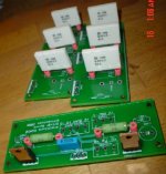
pinkmouse said:Jacco, got any pics yet?
Sort of, still waiting for Mark's ThermAlloy insulators before i can mount output devices.
a couple of weeks ago my physiotherapist did some bonecracking on me for a painfull shoulder.
He managed to displace an intervertebral disc in my neck, which gave me headaches and blurred vision.
Very hard to see small resistors and the point of a soldering gun, even worse for someone wearing reading glasses, i assure you.
Beware of bone manipulators !
Posting a pic of a main board tomorrow, digcam ran out of juice.
Attachments
- Home
- Amplifiers
- Solid State
- Krell KSA 50 PCB