Hi,
has anyone on the Canada/US side asked Plitron if their LONO, Lostray & UST transformers can match the spec of the Avel?
Their (semi-techy) blurb sounds impressive.
http://www.plitron.com/lono.asp
And their pricing might suit you.
has anyone on the Canada/US side asked Plitron if their LONO, Lostray & UST transformers can match the spec of the Avel?
Their (semi-techy) blurb sounds impressive.
http://www.plitron.com/lono.asp
And their pricing might suit you.
Hey all,
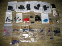
I finally got most of the components needed to start building (still need a few transistors and N-channel FET's), and since the component spec is so high I just had to post a picture of it. This is for four channels, one set to upgrade an existing commercial Mk1 to a high-end Mk2, and the other to build a no-holds-barred DIY version with all the tweaks possible.
Shown are all the passive components. At the top, Panasonic FC 1000uF 63V. Below it left are 220uF 63V. The white caps are Mundorf 1uF film
Top right are IXYS soft-recovery high-current rectifiers. The red caps are Black Gate NX for the feedback. Next to it Black Gate 10uF for the diode bypass, below it RELCap Teflon&foil for the 680pF input cap. Next to it, Black Gate 100uF 100V. The blue ones are Vishay MKP1837 100nF.
All the electrolytics besides the red ones and 10uF's are for the CP's. Next to that, silver mica for the other pF values. On the right, the output snubber RC filter, M-CAP 100nF and 5R6 Mills. Below that, output stage emitter resistors, 0R47 Mills. All the blue resistors: Riken 0.5W and the red ones PRP. All the parts shown are about $750.
Overkill? Definitely, but at least I'm fairly confident that it's the most esoteric DIY Krell that's ever to be built. The only areas for improvement would be replacing all the CP electrolytics with Black Gate NX's and the film caps with M-CAP Supreme's or so, but somewhere one needs to stop ;-) Transformers will be dual 1.5kVA's, and PSU caps if budget allows Mundorf M-Lytic 47000uF 80V, also steeply priced at $130 EACH.
I think we should all give Jozua a hand of applause for taking this project to a new level since it's for him that I'm building this and thus his expense.. and a silent prayer for yours truly to not blow something up
Attachments
Costly Clone
Pierre
I dont know about applause but you need to remember this is the LAST major DIY project for me.
Consider it a vote of conficence in you.
It also important that we get some feedback on this forum re the board assembly to keep the interest in the project alive.
Jozua
Pierre
I dont know about applause but you need to remember this is the LAST major DIY project for me.
Consider it a vote of conficence in you.
It also important that we get some feedback on this forum re the board assembly to keep the interest in the project alive.
Jozua
Heatsinks
Has anyone tried a DIY heatsink? I came across this website that describes a technique for making a heatsink. You can alter the size of the plates/fins to work for your individual project.
We have a local shop that will laser cut aluminum sheets if provided with a CAD file. If I can find someone to make the file for me I thought I might give it a try. Laser cutting from a CAD file would ensure the holes and cuts are perfect. You could probably paint or anodize once it is assembled. I don't know the cost, but am guessing that it may be cheaper than big machined heatsinks. It also crossed my mind to cut the fins from a sheet of copper, but haven't explored the cost of doing so. Copper fins would allow a smaller heatsink I believe. Any thoughts?
The link is: http://sound.westhost.com/articles/diy-heatsink.htm
Paul
"Any thoughts?"
Most heat sinks are extruded not machined, and there is no way around it, big hunks of metal formed to dissipate heat will cost lots of money.
Conrad has the best product to price gig.
BUT... You could do some fancy hi-fa-uten heat sinks if you were going to roll your own.
In the case of a Krell, it is most PRACTICAL to used forced air.. Not desirable, but practical.
troystg said:Most heat sinks are extruded not machined
Not the high power types, matey.
Paul,
i've done a lot of diy heatsink stuff, at the time when it was very hard to find high performance models.
CNC, lathing, with crimping the fins and argon-arc alumiuim welding(tig and/or mig for modern blokes)
There are some threads here on diy heatsinks, i've posted on a few.
Worthwhile, if you have cheap aluminium/copper resources and think exotic. Like the high fin density types i have for Bruno Putzey's ExtremeA amps.
A real beaut to diy is a model that has a large number of closely grouped circular rod fins, seen it used on a commercial amp.(got a picture of it too,..somewhere)
Hi,LineSource said:With some thoughtful chassis design simple copper plates can provide good heatsinking. The heatsink must be a couple inches off the ground to create a thermal chimney to pump out the hot air mass.
this copper plate idea is probably workable upto about 100W of dissipation. A bit short of what a KSA50 Klone requires and well short of the 270W required for a KSA100 Klone.
You can reduce that 10mm gap down to about 6mm with a passive heatflow sink. Those 3inch (75mm) fins will need to be about 6mm to 8mm thick to give effective heat distribution if made from aluminium, In copper this could be reduced, possibly as low as 4mm to 6mm and still retain reasonable efficiency.
Pollypocket
I have made a number of diy heatsinks.
I use three u sections of aluminium fitted inside each other and fastened on the outside of an aluminum case. For one set of heatsinks use a 50mmdeep x 100mm wide u section. inside that place a 75mm x 75mm u section and inside that place a 100mmdeep by 50mm wide u section and bolt all together on the outside of the chassis. I use 5mm aluminum sections. I fasten 3 such heatsinks on each side of the power amp casing. The heatsinks can be as high as you want them. I find about 1 output device per 50mm of heatsink works fine for 20w disipation of heat.
This looks neat and does not involve any sppecial metalwork except cutting u section and drilling holes.
Don
DIY Heatsinks
Don,
Thanks for your post on the U section heatsinks.
Is there a particular source for the U sections in the UK that you use?
Don,
Thanks for your post on the U section heatsinks.
Is there a particular source for the U sections in the UK that you use?
Don;
I am trying to visulize your description...any photos of your design?
Regarding Andrew's assertion on the DIY heatsink not being big enough for the KSA100...could one not just make the plates larger, ie; more surface area and get to the 270W dissapation level?
The DIY heatsink is appealing to me as big commercial heatsinks are expensive, and expensive to ship.
Also, has anyone considered liquid cooling? There are a number of kits available for overclocking CPU's in computers. The original designs were DIY and a little scary (liquid running through plastic hoses in my computer!!). However, there are a number of commercial designs available now. I am thinking I could put one heatexchanger (designed for a CPU) onto each output tranny and have a central cooling radiator outside the amp box. Unconventional but interesting.
Paul
Barry blue
Hi
After re- reading my e mail I am surprised that you could understand what I tried to describe. However if you could understand the idea I think you will find that it works well. I have used this technique for some time as it allows a professional looking heatsink of any size to be made. For a 60 w class a monoblock I use three sets of heatsinks on either side of the amplifier and make them 150 to 200 mm deep.
I use Outlook Stockholders in Coulsdon Surrey. They are a small company and local to me and for cash they offered the best prices.
Don
Hi
If I try to describe the heatsink more easily it is 3 heatsinks inside each other. A 100 x 50 inside a 75 x 75 inside a 50 x 100 section.
Don
If I try to describe the heatsink more easily it is 3 heatsinks inside each other. A 100 x 50 inside a 75 x 75 inside a 50 x 100 section.
Don
Whose building already
Hi
I am somewhat concerned that nobody seems to be giving any feedback on how their projects are progressing? I seem to remember a much more active KSA 50 thread....
If there are common assembly problems we need to discuss it here.
Alternatively has the realisation that this is a daunting project only kicked in now? If so has anybody considered simply downgrading the project by swopping their existing KSA 50 boards with a KSA 100 board to evaluate the sound?
Where are the stallwarts like Pinkmouse (what a name!!) and Troy.... etc?
Let's not allow this project to fade....
Jozua
I have similar concerns.. is it simply a matter of everybody still waiting for their diodes?
I only got my boards a week ago and already almost finished with two channels', including milling all the board heatsinks, and should hopefully have them playing sans output stage by the end of the weekend. Then its only dropping them onto an existing output stage and power supply and all systems go.
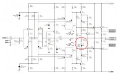
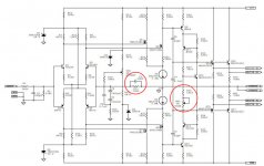
A swopout with a KSA50 will not work unless the voltage rails are high enough or the resistor and zener values for the LTP current sources are adapted.
I only got my boards a week ago and already almost finished with two channels', including milling all the board heatsinks, and should hopefully have them playing sans output stage by the end of the weekend. Then its only dropping them onto an existing output stage and power supply and all systems go.
A swopout with a KSA50 will not work unless the voltage rails are high enough or the resistor and zener values for the LTP current sources are adapted.
- Home
- Amplifiers
- Solid State
- Krell KSA 100mkII Clone