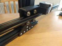
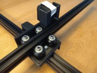
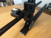
Right now the methods used to move the mic vertically and horizontally are leaning towards a freely sliding plate on Vee groove rollers moved by a pinion gear against a rack gear. It's an elegant system. Cost effective and relatively easy to make. It does not hold it's position if the motor is off. It will in fact free wheel to it's point of bottoming out. Vertically it will slide down to the bottom, horizontally it may keep it's position.The motors are off when a measurement is made, so why would their noise be an issue?
There is an ACME or trapezoidal thread and nut system. It self locks. Belt and pulley will free wheel. So will a ball screw.
Simple in one way, not so simple in others.
Hence my call for motors with brakes. Hence the return answer of a TI chip motor controller that is known to allow fairly quiet static motor positions.
Personally I am wondering if there is a simple motor brake system that is normally braked, and actuated upon command. That would probably be the simplest, and least noisy.
A looking I will go.
Like the idea of using a 3D printer control package. As plug and play as is possible. Just needing rewiring for extra cable length and probably cable chains to keep everything tidy and protected.
Last edited:
https://www.aliexpress.com/w/wholesale-NEMA17-with-brake.html?spm=a2g0o.detail.search.0
I looked on Amazon.ca and it's double the cost.
Am I correct in determining that the motor doing the vertical lifting is the one that will need the most force. I guessed at the motor. I have not calculated the loads. The duty cycle is rather large considering the length of time required to do the measurements. Few's idea of a counterweight is tried and true used on Vertical CNC milling machine tools for decades. Our trouble is keeping it compact enough to be practical.
Last edited:
I would think that the vibrations here would be an insurmountable problem if they get to the microphone. Any vibrations in the structure during a measurement will be problematic.The motor for the vertical motion would have to stay on
Hard to argue when you are right Earl.I would think that the vibrations here would be an insurmountable problem if they get to the microphone. Any vibrations in the structure during a measurement will be problematic.
What about a spindle? That should be self-blockingunless there is a well-balanced counter-weight to fight gravity
Been there, done that.That sounds like me. However...
This time I'm doing things differently. I'm getting some stuff and will find out in real life. The cost of actual stuff doesn't outweigh the time (and frustration...) I would need to spend on CAD. For other people this balance might be different.
Result is very often tons of unfinished projects (diy, private as well as professionally) on the shelves.
Besides that it eats space, I don't wanna think about how much money went into these unfinished projects.
These days I always work with a feasibility study.
Not just on a technical level, but also practical level.
With thought experiments as well a Fermi approach you can perfectly guess if a project is going to make sense or not.
Well, unless you're in for just sake of spending time and effort to just do something of course.
I can't speak for other people, but I have done so many similar projects that I had my fair share amount of these. 🙂
I don't know about your floors, but mine (and the vast amount I have seen) are far from being smooth and straight.Here's an attempt to clarify what I tried to describe back in post 1338. I'm not pushing anyone in this direction, I just figured I'd post the images since I now have them. The mic would be inserted in the end of the blue cylinder, which extends from an aluminum V-extrusion that rides on four wheels for radial motion of the mic. Another four wheels (see second drawing) provide vertical motion along the green extrusion. Angular motion is centered around the red lazy Susan which supports a piece of plywood. The other end of the plywood is supported by two small red wheels. A belt driven by a stepper motor wraps around a plywood disk concentric with the lazy Susan. A pedestal of suitable height could fit through the hole in the lazy Susan and plywood.
Few
View attachment 1293267View attachment 1293268
The steppers of my CNC are extremely hard to move (basically not at all) when they are turned off when you try to push the axis.The motor for the vertical motion would have to stay on to maintain position unless there is a well-balanced counter-weight to fight gravity. Not having a weight swinging on a string would be nice, if possible. A brake is another option, but that's another complication that would be nice to avoid. A motor that can hold its position quietly seems simplest.
Regarding the V-wheels vs. linear rails: for a CNC router, with all the cutting forces, heavy spindle, and need for accuracy down to tens of microns, V-wheels would sure seem inadequate (I'm surprised such systems persist on the market). But to hold a mic in position, and locate things within a couple of mm? Seems like the much lower weight and cost of V-wheels and Al extrusions are a good option.
Few.
This is mostly because of how the gears are perpendicular to shaft.
It kinda auto locks that way.
When you just turn the shaft of the stepper it's easy.
The silent stepper drivers for 3D printers are quite cheap but they only stop the R2D2 noise which is only a problem while the stepper is moving.So we need one that is commonly available, has the current capability to drive the motors we want, and the fancy TI chip that allows silentish operation? Cause I know FDM printers are damn noisy with those steppers.
Actually motor noise is probably going to be our largest problem after all other dragons are vanquished.
I'm not sure how well they perform when being used to apply holding torque, 3D printers don't really do that.
Braked steppers are a simple solution, in terms of the overall price for building a system like this I don't think it should break the bank.
Another alternative is a worm drive gear as that cannot be back driven. Using gearing can help small steppers to work instead of bigger ones. Less holding torque means less noise.
The 3D printer board itself doesn't matter that much as long as it works with the steppers chosen. The movement would be down to sending gcode which is already universal. It would have an effect on what kind of firmware and physical interface that can be used for manual adjustements and setup.
V-wheels work and are cheap which is why they are popular. I just find them to be nasty. They are painful to adjust for low friction without becoming too loose. High friction causes the need for more torque in the motors, more weight, more noise etc. It looks to me that Klippel is using belt drive with linear rails and bearing blocks, that makes sense to me.Regarding the V-wheels vs. linear rails: for a CNC router, with all the cutting forces, heavy spindle, and need for accuracy down to tens of microns, V-wheels would sure seem inadequate (I'm surprised such systems persist on the market). But to hold a mic in position, and locate things within a couple of mm? Seems like the much lower weight and cost of V-wheels and Al extrusions are a good option.
I like linear rails too. Simple, not too expensive. And no adjustment.
As b_force pointed out, a stepper will self cog when the power is off. The force required to overcome that cog effect could be mitigated with a counter weight. Again the worm drive idea is a great one, not possible to back drive a worm gear.
What I am seeing is helpful, and a few people have great ideas that they will be enacting. NEMA 23 a large enough motor?
And I understand the basics of how a 3D printer controller works. And the movement via the g-code. As long as the printer driver will provide enough current with a healthy safety margin, and there is an appropriate cooling system for near 50% duty cycle. We should be fine!
I was troubled by visions of a freely swinging counterweight banging into things and taking forever to settle after an angular motion. However, if there were instead pulleys at the top and bottom of the vertical post, with a cord in the shape of a tensioned loop wrapped around both pulleys, a weight could be fastened to the loop to counteract gravity tugging on the mic mount. The tensioned loop could keep the weight from swinging.
Or, if a 40x40 V-groove extrusion were used for the vertical post, one set of V grooves could constrain the motion of the mic boom, and the other parallel set of grooves on the other half of the post could constrain the motion of a second plate with its own set of wheels. Weight on that plate could serve as a well behaved counterweight for the mic boom.
Since I’m still envisioning V-grooves, I think this latter approach would be less fiddly and less likely to allow a weight to bang around. Either way, the motor could just be turned off without having to complicate the drive mechanism with worm gears etc., and without brakes.
By the way, thanks to all for the constructive discussion. I find the haggling about design decisions helpful because it keeps me from getting stuck on whatever notion first enters my head. If more than one project comes to fruition it will be interesting to see how the various designs work out.
Few
I'm having random 'crashes' with arduino (clone) and grbl. Searching the internet shows I'm far from the only one and a clear problem/solution is not available.
It turned out to be a crappy arduino clone board. Running fine now. This is how you use it in octave:
Code:
grbl_move(grbl, x, y, z);That's all.
My 2020 aluminum profiles are somewhat delayed. I hope to get them on monday.
My first thoughts for the motion system might not have been that weird after all:
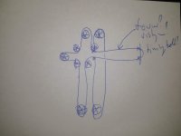
Definitely the same vibe. Pro would be that the motors are stationary.
Edit: It seems to be called T-Bot: https://www.buildlog.net/blog/2017/10/the-midtbot-a-new-flavor-of-h-bot/

Definitely the same vibe. Pro would be that the motors are stationary.
Edit: It seems to be called T-Bot: https://www.buildlog.net/blog/2017/10/the-midtbot-a-new-flavor-of-h-bot/
Last edited:
I will look !My first thoughts for the motion system might not have been that weird after all:
Might be a great idea.
Table top NFS:
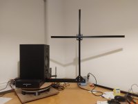
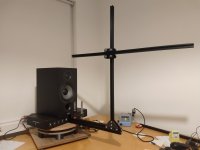
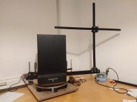
This was the easy part 🙂
Friction is keeping the horizontal arm where it is. Of course that will change with a microphone, but my guestimate is that the stepper should have no problem keeping that at the desired position.
The flexibility is a point of concern. I have an extra 2020 profile that I could add.
Now I will need quite some time to get it moving. The internal gear rack is probably the easiest solution. However, if we could keep the steppers on the turntable, the steppers are stationary (so no moving electrical wires) and the arm light.
Anyway, I will have to fight with Fusion, 3D print stuff and order things. But now I at least have something tangible to think about and look at.
Ps. Of course the speaker should not rotate.
Last edited:
Just an update, nothing special:
Although I would love to make a belt driven motion system with the steppers and control box on the turntable, I'm too unfamiliar with CAD and the mechanics and where to source the materials, that I've chosen to go the direct drive route; at least for now 🙂
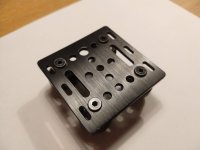
The wheels of the gantry plate are attached to the plate with screws. The heads are protruding a bit. We need to mount two of these gantry plates back to back and rotated 90 degrees. The plate below allows that:
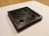
Attached to (one) profile, that looks like this:
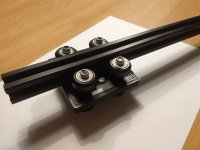
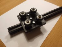
Now we need a mount for the stepper. Both steppers will be attached to the gantry plate combo. A (lucky) benefit is that all the mass is close to the vertical profile, so not much bending because of the steppers.
My CAD skills don't allow fancy shapes, so the stepper/gantry mounting piece a little boxy. Here is it with a single gantry plate attached:
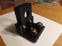
And with a (3D printed) stepper model and profile it looks like this:
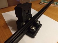
And here is the first problem: The motor is probably too far from the proflle. The stepper torque is ~40Ncm, the arm is 3cm, which results in a little more than a kilogram of 'force'.
And finally an impression of the complete gantry thingy:
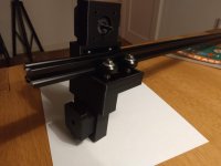
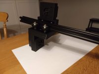
Although I would love to make a belt driven motion system with the steppers and control box on the turntable, I'm too unfamiliar with CAD and the mechanics and where to source the materials, that I've chosen to go the direct drive route; at least for now 🙂

The wheels of the gantry plate are attached to the plate with screws. The heads are protruding a bit. We need to mount two of these gantry plates back to back and rotated 90 degrees. The plate below allows that:

Attached to (one) profile, that looks like this:


Now we need a mount for the stepper. Both steppers will be attached to the gantry plate combo. A (lucky) benefit is that all the mass is close to the vertical profile, so not much bending because of the steppers.
My CAD skills don't allow fancy shapes, so the stepper/gantry mounting piece a little boxy. Here is it with a single gantry plate attached:

And with a (3D printed) stepper model and profile it looks like this:

And here is the first problem: The motor is probably too far from the proflle. The stepper torque is ~40Ncm, the arm is 3cm, which results in a little more than a kilogram of 'force'.
And finally an impression of the complete gantry thingy:


Still chasing the T-bot idea?
From your setup pics, I am guessing you are not looking to measure any farther away than 0.5 meters?
From your setup pics, I am guessing you are not looking to measure any farther away than 0.5 meters?
- Home
- Design & Build
- Software Tools
- Klippel Near Field Scanner on a Shoestring
