Brian,Given that net box volume, I was able to come up with a singe-expansion TH for the 4 ohm version of the 18TBW100 that can fit in it with an Fb of 30 Hz and mouth area of 1820 cm^2 (282 sq.in.). With suitable cone compensation, the response of the TH is basically flat from 100 Hz down to Fb. Path length is around 339.4 cm and compression ratio is 2.23. Passband SPL is about 100dB/2.83V/1M.
If you want, I can provide a panel list to an MTH-30 type of layout for the TH I described above. If anything, it can be useful for comparison purposes.
Build your design and measure it- that would be useful for comparison purposes ;^).
Art
Last edited:
I'll post pictures when the cabinets are finished and painted, but they look pretty much like the original- just 4.5" taller.Are you going to post pics of the B-lows? I like how the neighbor's chest was hurting!
Brian,
Build your design and measure it- that would be useful for comparison purposes ;^).
Art
Alas, I might not be building stuff for awhile. I suffered a minor stroke last Sunday and I'm still in recovery. Right side is still weak and I'm walking like a flippin' zombie Jack Sparrow and suffering minor bouts of dizziness. Falling on my circle saw is not on my to-do list - SWMBO would kill me if the circle saw doesn't 🙂. Plus, for a useful comparison, I'd have to build both the B-Low and the upsized MTH-30, and I don't happen to have an 18TBW100 on hand...
Brian,Alas, I might not be building stuff for awhile. I suffered a minor stroke last Sunday and I'm still in recovery. Right side is still weak and I'm walking like a flippin' zombie Jack Sparrow and suffering minor bouts of dizziness. Falling on my circle saw is not on my to-do list - SWMBO would kill me if the circle saw doesn't 🙂. Plus, for a useful comparison, I'd have to build both the B-Low and the upsized MTH-30, and I don't happen to have an 18TBW100 on hand...
Excuses, excuses- at least your sense of humor is intact!
Work with SWMBO, and best of luck in your recovery.
I highly recommend Norman Doidge's book "The Brain's Way of Healing", chapters 3 and 7 specifically for you. There is a lot of info in the book that typical physicians and their patients are not aware of that can be really helpful for all sorts of brain problems.
Cheers,
Art "Titanium Cranium"
Brian,
Excuses, excuses- at least your sense of humor is intact!
Work with SWMBO, and best of luck in your recovery.
I highly recommend Norman Doidge's book "The Brain's Way of Healing", chapters 3 and 7 specifically for you. There is a lot of info in the book that typical physicians and their patients are not aware of that can be really helpful for all sorts of brain problems.
Cheers,
Art "Titanium Cranium"
Thanks. Right now while in "recovery mode", I can do about 15~30 minutes of keyboard-warrioring (e.g. I just finished what I hope is a decent sim for the 10" version of the Wicked One), and maybe a little fondling of the power tools. SWMBO gave me some strange looks when I mentioned using a hole-saw on my "Uglito" sub to convert it to 6th order BP, so maybe that can wait until tomorrow when she won't be around 🙂.
The Fb not dropping with the longer B-Low path length is a real mystery, I can't think of any reason why it wouldn't.
I think I'm a bit closer to solving that particular problem. The Keystone fold is a bit like the MTH30 fold, with S1 starting a bit further up, so I tried using the external dimensions you provided for the B-Low in the spreadsheet, and the expansion up to the minimum mouth size you mentioned basically does not work if the depth is kept at 22.5". For a smooth expansion the depth needs to be 28.5", which of course significantly increases the volume of TH and reduces Fb into the 20's.
I may mod the MTH30 spreadsheet I have to allow a Keystone-type layout as an option, but I suspect that it will confirm what I'm saying above.
Attachments

I think I'm a bit closer to solving that particular problem. The Keystone fold is a bit like the MTH30 fold, with S1 starting a bit further up,.
Aargh, no it's not. I mixed up the folds. Ignore the rest, sorry!
Brian,I think I'm a bit closer to solving that particular problem. The Keystone fold is a bit like the MTH30 fold, with S1 starting a bit further up, so I tried using the external dimensions you provided for the B-Low in the spreadsheet, and the expansion up to the minimum mouth size you mentioned basically does not work if the depth is kept at 22.5".
Edit: too late to ignore you :^)
The MTH30 has an additional fold than the Keystone.
The B-Low is identical to the Keystone, other than the vertical panels are extended by 4.5", 10% longer, also expanding volume by 10%.
I don't understand your larger volume cabinet with an extra fold explaining why the relatively straightforward changes in my design did not result in the predicted response.
Then again, the original Keystone never did conform to the Hornresp sim exactly, so it not conforming to the dropped Fb predicted does not surprise me too much.
Bottom line, the taller Keystone is a little louder overall than the original, can put out 124 dB at 30Hz, 143 dB at 100Hz as tested.
I also plan to make a removable "step down" panel that should result in peaks around 127 dB at 30Hz, 136 dB at 40 Hz, 140 dB at 90 Hz.
I will need to find a new place to test that loud however, as I don't want to bother my neighbors again
 .
.Cheers,
Art
The MTH30 has an additional fold than the Keystone.
Yep, that's what tripped me up. Because it has that extra fold, the cabinet ends up being shorter and deeper to achieve the same smooth expansion.
Then again, the original Keystone never did conform to the Hornresp sim exactly, so it not conforming to the dropped Fb predicted does not surprise me too much.
There is that. The Keystone, as described in post #487(?), apart from its unique mouth shape, seems to have three expansion rates going on between what appears to be the best choices for the position of S2 and S3, and of course Hornresp can only accommodate one.
Seeing that I'm still confined to the keyboard (SWMBO said no cutting of any holes in any speaker boxes while she's around, so the "Uglito" mod will have to wait), and I *hate* unsolved mysteries, I think I'm going to mod the MTH spreadsheet to have it describe the Keystone, with some of the internal panels adjusted to keep a smooth expansion between S1 and S3, then see what Hornresp has to say. I suspect the answer lies in the assumed length for section L45, which might be shorter than expected. If I succeed, and that's a big IF, that means that I might end up with an optimization routine for a Keystone alignment, allowing its size and layout to be easily adjusted to match a driver's specs. If I succeed 🙂.
Brian,The Keystone, as described in post #487(?), apart from its unique mouth shape, seems to have three expansion rates going on between what appears to be the best choices for the position of S2 and S3, and of course Hornresp can only accommodate one.
Seeing that I'm still confined to the keyboard (SWMBO said no cutting of any holes in any speaker boxes while she's around, so the "Uglito" mod will have to wait), and I *hate* unsolved mysteries, I think I'm going to mod the MTH spreadsheet to have it describe the Keystone, with some of the internal panels adjusted to keep a smooth expansion between S1 and S3, then see what Hornresp has to say. I suspect the answer lies in the assumed length for section L45, which might be shorter than expected. If I succeed, and that's a big IF, that means that I might end up with an optimization routine for a Keystone alignment, allowing its size and layout to be easily adjusted to match a driver's specs. If I succeed 🙂.
I'd suggest looking at TB46 Hornresp inputs in post #96, and Djim's #127-130.
If you want to really "dial it in" you will need to use Akabak to come close without a lot of fudge factor.
Good luck,
Have fun!
Art
Brian,
I'd suggest looking at TB46 Hornresp inputs in post #96, and Djim's #127-130.
If you want to really "dial it in" you will need to use Akabak to come close without a lot of fudge factor.
Good luck,
Have fun!
Art
I'm going to "greenfield" this one and describe the layout of the Keystone in the workbook and let it come back with the suggested Hornresp parameters. Then I'll compare the results to the info in the posts you mentioned. Wrt the varying expansion between S1 and S3, I'll bet that the sim will still be accurate enough once I've got S1, S3 and the path length close enough. It's S5 and L45 that are going to be challenging - I may have to use your measurements to determine the "effective" value of L45 to give the measured Fb. So yes, there's going to be some fudging, but I think if there are going to be any major differences between the sim and the build, they're going to appear at the upper end of the passband, which is going to be affected by the frontal area of the Keystone anyway.
I've already got the layout of the Keystone down in the workbook, so tomorrow it's a matter of mapping out the path, and then inserting the optimization routines. Right now it's time for bed before SWMBO bans me from the computer too...!
Attachments
I've already got the layout of the Keystone down in the workbook, so tomorrow it's a matter of mapping out the path, and then inserting the optimization routines. Right now it's time for bed before SWMBO bans me from the computer too...!
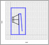
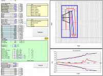
...and we're a little closer today. I've got the path mapped out, based on the internal dimensions and panel layout for the KS. I've moved S3 to the top of the horn, as that should the accuracy of the Hornresp sim a bit. From the expansion graph it looks like the expansion is just slightly off at the stop and near the front (section A in the image), which will have the effect of increasing Fb, the equivalent of shortening the path length. Next step is to take the parameters generated by the workbook and input then into Hornresp. I suspect that the predicted Fb is going to less than what you measured, because of how the mouth of the horn is implemented. My intent is to adjust L45 in the sim to compensate (section B in the image), then modify the workbook to reflect an "effective" path length in its calculations.
...after I wash the dishes before SWMBO comes home and sees them... 🙂
Attachments
1) Are you working on the original or the taller (B-Low) dimensions? In either case, the cone area in the throat and the speaker volume in top front affects the flare.1) I've got the path mapped out, based on the internal dimensions and panel layout for the KS. I've moved S3 to the top of the horn, as that should the accuracy of the Hornresp sim a bit. From the expansion graph it looks like the expansion is just slightly off at the stop and near the front (section A in the image), which will have the effect of increasing Fb, the equivalent of shortening the path length.
2) I think if there are going to be any major differences between the sim and the build, they're going to appear at the upper end of the passband, which is going to be affected by the frontal area of the Keystone anyway.
3)I suspect that the predicted Fb is going to less than what you measured, because of how the mouth of the horn is implemented. My intent is to adjust L45 in the sim to compensate (section B in the image), then modify the workbook to reflect an "effective" path length in its calculations.
...after I wash the dishes before SWMBO comes home and sees them... 🙂
2) Both upper and lower response are affected by the Keystone area and position.
3) It's easy to "predict" something that has already happened, that is the sim for the longer path length did not come in with a lower Fb- it was pretty much the same as the shorter Fb, though drops more with a similar area reduction, IIRC.
1) Are you working on the original or the taller (B-Low) dimensions? In either case, the cone area in the throat and the speaker volume in top front affects the flare.
I'm working with the original. Once the parameters generated by the workbook produce a sim that has the same Fb as the KS, then I'm going try it out using the B-Low's dimensions to see if it successfully predicts what you observed wrt Fb. The workbook takes into account the cone volume at the throat and the impact of the speaker volume in the mouth will be taken into consideration when determining the effective S5 and length for the L45 section.
The nifty thing here is that once the workbook produces an accurate enough sim, then its optimization routines can be used to optimize the layout of the horn (that is, tweak the layout of the internal panels to make the result a closer match to the generated Hornresp parameters for the horn) and run a few "what if" analyses. e.g. what if the KS is slimmed to 24" and its depth increased to 24"? Enter these dimensions into the workbook, run the optimization routine, then import the parameters it generates into Hornresp for viewing. Takes all of 5 minutes to do 🙂
I'm working with the original. Once the parameters generated by the workbook produce a sim that has the same Fb as the KS, then I'm going try it out using the B-Low's dimensions to see if it successfully predicts what you observed wrt Fb. The workbook takes into account the cone volume at the throat and the impact of the speaker volume in the mouth will be taken into consideration when determining the effective S5 and length for the L45 section.
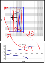
Here's where I've reached so far. As expected, the effective path length of the KS does not reach all the way to the bottom of the cabinet because of the location and shape of the mouth. In fact, I think I'm being a little optimistic in this sim with L45, because I suspect that the HornResp sim has the S1-S3 section larger than it actually is, which will drive predicted Fb up. Anyway, it's a start. Box losses will likely melt way that 3dB narrow peak at the lower end of the passband, and the size of the front of the KS will lead to the measured response at the upper end of the passband being higher than predicted by the sim. And then there's the effect of the mouth shape, of course 🙂.
Attachments
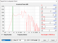
The 4.5” taller Keystone B-Low is a “qualified success”. According to simulations, the longer path length should have dropped the Fb (the minimum excursion point for the driver) to 29.65 Hz, with an F3 of 31 Hz. It did not. The first test using an exit of 416 square inches had a 35 Hz Fb. Reducing the exit to 267 square inches dropped Fb to 34 Hz, and reduced excursion around Fb. With a 207 square inch exit, the Fb drops to 33 Hz, increasing available output at 31 Hz (the “Low B” note) by 2 dB over the 34 Hz version.
What I've come up with so far, based on the sim:
1. 416 sq.in. seems a bit large for this particular alignment. S4 is in the range of 265 sq.in. and the mouth should probably be around 275 sq.in., if placed at the bottom of the cabinet, and should be smaller if place further up the face.
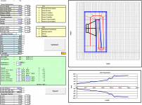
2. If all was done was to extend the vertical panels, then this could lead to part of the horn expansion being a bit smaller than required for a smooth expansion. Leaning the baffle by 2 degrees instead of 1 can using an offset 2.3+2 = 4.3 degrees for the other internal panels can alleviate this. The expansion between S2 and S3 would then be quite close to a conical expansion (see image below - the dotted red line is ideal conical expansion). This does bring the speaker's magnet pretty close to the front though! Increasing the depth of the cabinet by 0.5 or more inches might help.
3. Optimization? Well, that's not going to work. The optimization routines in the workbook are built around parabolic expansion segments, the shallow depth of the cabinet and that large increase between S3 and S4 and that offset baffle are tripping them up. I might redo the routines to look at conical expansion instead, after the math required stops turning my brain into mush.
Attachments
What I've come up with so far, based on the sim:
1. 416 sq.in. seems a bit large for this particular alignment. S4 is in the range of 265 sq.in. and the mouth should probably be around 275 sq.in., if placed at the bottom of the cabinet, and should be smaller if place further up the face.
2. If all was done was to extend the vertical panels, then this could lead to part of the horn expansion being a bit smaller than required for a smooth expansion. Leaning the baffle by 2 degrees instead of 1 can using an offset 2.3+2 = 4.3 degrees for the other internal panels can alleviate this. The expansion between S2 and S3 would then be quite close to a conical expansion (see image below - the dotted red line is ideal conical expansion). This does bring the speaker's magnet pretty close to the front though! Increasing the depth of the cabinet by 0.5 or more inches might help.
3. Optimization? Well, that's not going to work. The optimization routines in the workbook are built around parabolic expansion segments, the shallow depth of the cabinet and that large increase between S3 and S4 and that offset baffle are tripping them up. I might redo the routines to look at conical expansion instead, after the math required stops turning my brain into mush.
1) I started with a larger exit with the larger cabinet, the original Keystone had optimal response with 314 square inches ranging from the bottom to above the magnet structure, also allowing for excellent cooling. The taller "B-Low", still has the magnet structure "exposed", requiring the smaller 207 square inch exit for optimal "rock" response, and employs a reduction plate for when one prefers to trade response above 40 Hz for response below 40 Hz.
2) The minor changes would have minimal effect, certainly less than the exit shape, position and area, all of which were optimized in the original design, which is made to fit specific truck pack integers.
3) Brain exercise is good, but don't turn your brain into mush over a cabinet design that has already been optimized, and can't be accurately simulated with Hornresp 🙂!
- Home
- Loudspeakers
- Subwoofers
- Keystone Sub Using 18, 15, & 12 Inch Speakers