Hi, new on this site. Aquired a Kenwood KR-3130 and the right channel does not work...I can read a schematic, have a DMM, Oscope, and DBT. Would love to get some help troubleshooting this receiver. Can anyone Help?
thanks😕😕
thanks😕😕
Welcome to diyAudio 🙂
What have you checked so far?
Is the problem applicable to any input?
Have you checked the supplies to each power amplifier?
Is the midpoint voltage correct on each channel?
This is the DC voltage before the speaker coupling cap and should be approximately one half of the total supply voltage.
What have you checked so far?
Is the problem applicable to any input?
Have you checked the supplies to each power amplifier?
Is the midpoint voltage correct on each channel?
This is the DC voltage before the speaker coupling cap and should be approximately one half of the total supply voltage.
the problem is present on all inputs..I have my 20mA on the collectors of Q1 and Q4..My collector voltage on Q1 and Q4 is 48.3v which is correct. on the collector of Q2 i have 23.6v but on Q3 collector I have 31v...
The 31 volts is a bit indeterminate as regards a fault as normally the midpoint would swing one way or the other toward the rails.
Lets work with that though....
So the 20 ma bias current is correct and so you should be seeing approximately 9 millivolts (so very small voltage) across each of the 0.47 ohm emitter resistors.
The measured 31 volts midpoint should also be seen (approximately) on De2 which connects to the base of the driver transistors.
Its worth you working back from the output looking for any incorrect Vbe (base emitter) volt drops as that can be a good clue. Each transistor should have the base at approx 0.6 volts more positive than the emitter (for the NPN's) and 0.6 volt more negative for the PNP's.
The power amp is AC coupled up to Qe12 and so you are looking around just those five final transistors.
Its odd because a small problem that shifts the DC conditions wouldn't necessarily give no audio output. Something doesn't just add up here 🙂 Re74 and Re76 ultimately set the midpoint voltage but it would be unusual if there was a problem there.
Check those Vbe drops and see if that shows anything, and be careful not to short any pins out.
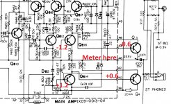
Another easy way to look at this is put your negative meter lead on the midpoint and then measure the voltage to each output transistor base and driver base.
For your 31 volts you should see:
31.6V on the base of Q4. So your meter should read +0.6
32.2V on the base of Qe14. So your meter should read +1.2
and
30.4 on the base of Q3. Your meter should read -0.6
29.8 on the base of Qe16. Your meter should read -1.2
The '0.6' is an approximate value related to the forward turn on voltage of a silicon junction. You are looking for large errors such as anything over say 0.8 volts or lower than say 0.4 volts.
Also check and compare the DC voltage across Re78 with the good channel.
Last edited:
Sorry... that post doesn't read well, you should see the 0.6 volt increases and decreases as you measure to each base using the midpoint as the reference.
Hope that makes sense.
Hope that makes sense.
midpoint for the neg. lead would be? sorry, this is the 1st receiver I have tried to work on, trying to understand as I go. Thanks
Yes, the unit is to be powered.
I'm going to repost what to expect as I've made some mistakes trying to describe it you. The upper NPN's that is Qe4 and Qe14 are as I describe and you should see the incremental change of 0.6V adding up as you work 'back'.
So with 31V on the emitter of Qe4 you should have +31.6 on the base and +32.2 on the base of the Qe14.
The PNP driver and the output Qe3 are where my description fell apart. The lower NPN output (Qe3) should see 0.6 volts between base and emitter.
The emitter is actually grounded and so we read between ground and base for that one.
The PNP driver (Qe16) will see about -0.6 to -0.7V measuring from the output (the midpoint) to the base.
Apologies for my errors describing that earlier. In essence all you are doing is checking the B-E volt drops which always are in the 0.6V region. Measuring from fixed points like the output is sometimes easier and safer than trying to prod two leads at once on a small device as one slip would be disastrous.
ok Mooly, on the base of Qe14 with respect to pin44 base of Q3...Qe14 is reading +48V and Qe16 base is reading +39V...that is way off. I did replace the Power Transistor Q4 which was originally 2SC1060 with a MJE3055 which I was told would be a match or cross. What do you think? oh yes on the base and emitter of Qe3 i am reading .627V
Last edited:
Those readings do sound off but lets be sure and let me try and make it easier to follow. If you have 48 volts from Qe14 base to the base of Qe3 then that really means the midpoint voltage should be very nearly equal to 48 volts... and you have 31. So 17 volts is being 'lost' across the base/emitter junction of Qe14 and Qe4. So yes, something is wrong there suggesting a possible open circuit junction in Qe14 or even open or broken print.
1/ Make sure you still have the same incorrect midpoint voltage of around +31 volts as measured from ground. If the reading is significantly different then just note down what it is and continue...
2/ Place you black meter lead on the midpoint position and read the voltage on Qe4 base with the red meter lead. You should read approx + 0.6 volts.
3/ Now place the red lead on Qe14 base leaving the black still on the midpoint. You should read 1.2 volts.
4/ Now place the red lead on Qe16 base. You should read approx -0.6 volts.
5/ Place the black meter lead on ground (chassis) and read the voltage on Qe3 base. It should be 0.6 volts.
The MJE3055 is an NPN power device and was very common years ago. It should work OK.
Had the 2SC device failed? Power transistors nearly always fail by going short circuit from C to E.
When I measure across Qe14 positive lead on base and neg. lead on emitter, I'm reading +19V and measuring Qe16 pos. lead on base and neg. lead on emitter, I'm reading +9V. can I measure like this?
Yes you can measure like that and tbh its my preferred method way as long as you don't accidentally short anything out 😉
So... for all NPN devices (where the emitter arrow points outward) you see no more than around 0.6 to 0.7 volts where the base is the more positive.
Any less and the transistor is either not being driven correctly or the device is leaky.
Any more and the B-E junction is open.
It would be unusual to have two faulty devices so you need to check you are identifying the leads correctly.
Qe14. Put your meter between pins 36 and 40 on the board. You should see 0.6 volts.
Qe16. Place your meter on the striped end of the diode D62 and the other lead on pin 46.
That gets you across the B-E junction of each driver.
Attachments
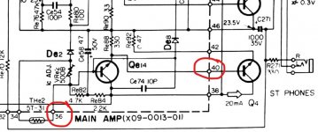
For Qe16 the emitter should be the more positive lead (its a PNP)
Have to go out now but I'll look in later.
Have to go out now but I'll look in later.
Ok, when I measure 2/ Qe4 base w/neg lead on Pin44 I read +1.2V
3/ with Neg. lead on Pin 44, Qe14 base is +48.5V
4/ with neg. lead on pin 44, Qe16 base is +39V
5/ with neg. lead on ground pin 49, Qe4 base is -1.8V
3/ with Neg. lead on Pin 44, Qe14 base is +48.5V
4/ with neg. lead on pin 44, Qe16 base is +39V
5/ with neg. lead on ground pin 49, Qe4 base is -1.8V
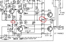
Qe4 base is pin 40 on my diagram, and pin 44 is the base of Qe3. The midpoint is pin 46.
There shouldn't be any truly negative voltages anywhere, that is voltages with respect to ground.
I'm going to post my copy of the diagram and the voltages between the pins. Give me a minute, then I have to go 🙂
There shouldn't be any truly negative voltages anywhere, that is voltages with respect to ground.
I'm going to post my copy of the diagram and the voltages between the pins. Give me a minute, then I have to go 🙂
- Home
- Amplifiers
- Solid State
- Kenwood KR-3130