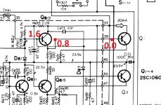
So you have 0V on Q1 base and approx 1.5V on the base of Q613.
Well the 'good' news is that also shows a problem. 0V on the base of Q1 means you should also see 0V on the emitter leg of Q613 as they are connected together.
If you have approx 1.5V on the base leg of Q613 then that means you should be seeing 1.5V directly across the B/E junction of Q613 and if so then that means it is faulty. The B/E voltage even at very high currents limits out at no more than around 0.8 volts.
So check carefully as before but this time the first thing to check is just to see if you have 1.5 volts across B and E by measuring directly on the legs (and be careful not short anything). That smaller type of transistor would be more likely to have this kind of fault... something you don't see in the big output type devices.
OK, lets work with that. As you will see, the devil is in the detail unfortunately.
If Q613 emitter is at 0.8 volts then you now have to reconcile why:
The base of Q1 and the emitter of Q613 are the same point. I think this is what you are describing... so is there a break between the base of Q1 and Q613 emitter?
(The bulb tester being dim is OK, that's normal)
If Q613 emitter is at 0.8 volts then you now have to reconcile why:
.Q1 is reading 0V
The base of Q1 and the emitter of Q613 are the same point. I think this is what you are describing... so is there a break between the base of Q1 and Q613 emitter?
(The bulb tester being dim is OK, that's normal)
Attachments
If you find a break and repair it then I would turn the bias preset back down to minimum before you retest.
Not doing so would allow maximum current to flow.
I'll look in later, good luck 🙂
Not doing so would allow maximum current to flow.
I'll look in later, good luck 🙂
Bingo, Mooly your the man.....found a break repaired the trace and wallah...great sound in both channels, also able to adjust the bias to 9.4mV...Thanks my friend! You are a great asset to diyaudio. Thanks!
- Home
- Amplifiers
- Solid State
- Kenwood KR-3130