next project Pioneer SX-525, no output!
And he turns the page...
That could be an interesting one 😉
I've decided to hold off on the Pioneer SX-525, have to order some parts. Now for the Kenwood KR-3130, both channels are working but, the left channel has distortion...right channel is fine. I thought I would check the bias and I'm not able to adjust bias on left or right channels, I should be reading about 9.4mV but I'm reading 0V. Any suggestions?
To get an idea of what is going on with the bias you first have to read the voltage between the two driver transistor bases and see what sort of voltage range you can get.
Replacement transistors may have different Vbe characteristics and so be out of range of what the circuit can provide.
So note down the max and min voltage between the driver base's and lets take it from there.
Replacement transistors may have different Vbe characteristics and so be out of range of what the circuit can provide.
So note down the max and min voltage between the driver base's and lets take it from there.
I assume your talking about Qe13 B-20.5V
Qe14 B-22V
Qe15 B-18.7V
Qe16 B-19.8V
are these the correct drivers?
I'm new at this so bear with me if you can...thanks
Qe14 B-22V
Qe15 B-18.7V
Qe16 B-19.8V
are these the correct drivers?
I'm new at this so bear with me if you can...thanks
Last edited:
QE613 is the upper NPN driver and QE615 is the lower PNP one.
You place your positive meter on the base of QE613 and the negative lead on the base of QE615. The voltage between these points should vary as you alter the bias preset. You need approximately 2.4 volts for the output transistors to begin to conduct and pass current.
It is around 2.4 volts because we need enough voltage to turn on the four base/emitter junctions of the drivers and outputs with each B/E junction dropping around 0.6 volts (give or take). These B/E junctions are effectively in series and so require that voltage to turn them on.
This explains why it is 0.6 volts for a silicon junction (well they say 0.7 here... you will find many transistors begin to come into conduction at slightly lower voltages)
Forward biased p-n junction diode
Attachments

Definitely enough for the 3 B-E drops of a quasicomp like that.
I suggest you verify that neither of the 33 ohm or 330 ohm resistors in the area have gone high.
Also, measure voltage across each 0.47 ohm resistor individually.
Verify that output transistor base connections are good.
I suggest you verify that neither of the 33 ohm or 330 ohm resistors in the area have gone high.
Also, measure voltage across each 0.47 ohm resistor individually.
Verify that output transistor base connections are good.
Last edited:
sgrossklass, thanks for the reply and help. I will check the resistors and FYI the base voltages are Q1 B-19.525V
Q2 B-.63V
Q3 B-.79V
Q4 B-21V
Q2 B-.63V
Q3 B-.79V
Q4 B-21V
also, R87-331 ohms
R89-32.4 ohms
R91-.6 ohms
R93-.6 ohms
when I put the test leads on each resistor, I read 0V, am I checking the resistor voltage correctly or should I be going across pins 44 and 45?
R89-32.4 ohms
R91-.6 ohms
R93-.6 ohms
when I put the test leads on each resistor, I read 0V, am I checking the resistor voltage correctly or should I be going across pins 44 and 45?
Last edited:
Definitely enough for the 3 B-E drops of a quasicomp like that.
You would certainly think so....
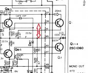
Lets continue with voltage checks and try this. Place your BLACK meter lead on the positive end of C171 of the speaker coupling cap. This is the main output line of the amplifier.
Now turn the bias preset to give the maximum voltage between the base of the two driver transistors as you did in the earlier post.
Now do three voltage readings using the RED meter lead.
1/ To the base of Q1. You should see approx 0.6 volts.
2/ To the base of Q613. You should see approx 1.2 volts.
3/ To the base Q615. You should read approx MINUS 0.6 volts.
Now transfer the BLACK meter lead to ground and read the voltage on Q2 base. It should be 0.6 volts.
here are the readings with black lead on +C171
Q1 base~ -18.5V
Qe13 base~ 1.5V
Qe15 base~ -.65V
moved black lead to ground Q2~ .7V
Q1 base~ -18.5V
Qe13 base~ 1.5V
Qe15 base~ -.65V
moved black lead to ground Q2~ .7V
here are the readings with black lead on +C171
Q1 base~ -18.5V
Qe13 base~ 1.5V
Qe15 base~ -.65V
moved black lead to ground Q2~ .7V
First reading shows a definite problem as it shows there is 18 volts between those two points.
Look at the circuit here. You are reading between these two points and so you should see essentially zero volts up to the emitter leg of Q1.
By keeping the black lead of the meter on C171 ( the + end) that means you should read zero volts on each leg of the 0.47 ohm Re91 and no more than around 0.6 volts on the base leg of Q1.
So you need to check carefully working back with the red meter lead first to the resistor and then back to the transistor. Something is open circuit there.
It could be physical such as broken print or a bad joint.
The resistor could be open in which case you would see zero volts on one end and 18 on the other.
The transistor could be open circuit between B and E but this is the least likely scenario at this point.
Attachments
- Home
- Amplifiers
- Solid State
- Kenwood KR-3130