Here we go.
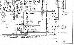
Black meter lead on 49, red on 44 and you should have +0.6 volts.
Black lead on 46 (and/or 42 as they should be similar) and red on 40 and you should have +0.6 volts.
Black lead on 46 and red on 36 and you should have +1.2 volts.
As a double check, black lead on 40 and red on 36 and you should now see +0.6 volt.
Black lead on 46 and red on the base of Qe16 and you should see -0.6 volts.
We want 0.6 volts between all the base/emitter junctions as shown. The base is the most positive for the NPN's
Attachments
1/ neg lead on pin 49, pos lead on pin44~.64V
2/ neg lead on pin 46, pos lead on pin 40~0V
3/ neg lead on pin 46, pos lead on pin 36~18.7V
4/ neg lead on pin 40, pos lead on pin 36~18.7V
5/ neg lead on pin 46, pos lead on base Qe16~+9.5V
2/ neg lead on pin 46, pos lead on pin 40~0V
3/ neg lead on pin 46, pos lead on pin 36~18.7V
4/ neg lead on pin 40, pos lead on pin 36~18.7V
5/ neg lead on pin 46, pos lead on base Qe16~+9.5V
new update, I was checking the solder connections and I found where someone had actually shorted the C to E on Qe10. I apologize, I should have already checked that before having you do so much work, I'm sorry! Now I have sound on both channels, but right channel is very low and distorted....what do you think? actually with further listening volume is good on left channel but does have some distortion..right channel volume is low with distortion.
Last edited:
Its no problem... just think of it as if Qe10 had been actually faulty and how we might have arrived at a diagnosis 🙂
First step is always to confirm the DC conditions are correct.
Is the midpoint OK on both channels now OK at around half supply voltage?
Now switch the amp OFF and do a careful check of the resistance of those four 0.47 ohm resistors. You can check them in circuit and we are not after great accuracy, just a quick check that they appear in the right ballpark.
Remember that if your meter leads are thin and have significant resistance then that will add to the reading and so you could easily read say 0.6 ohms or even a little higher.
Check all four though.
Now check that the bias current is correct. Do this by measuring the volt drop across those resistors. I think we said about 9.5 millivolts which would equal 20 milliamps.
Just refresh the page 😉 A vital word was missing.
You can check them in circuit and we are not after great accuracy,
The center voltage is 30V on right channel and 23.6 on left channel, output reistors Re92 Re94 Re91 and Re93 are 6 ohms. when I measure across Re92 I get 0V, same on Re91. also when I measure the output transistors collectors Q1~48.7V
Q2~23V
Q3~30V
Q4~48.8V
Q3 collector voltage is still high...
Q2~23V
Q3~30V
Q4~48.8V
Q3 collector voltage is still high...
Last edited:
1/ neg lead on pin 49, pos lead on pin44~.64V
2/ neg lead on pin 46, pos lead on pin 40~0V
3/ neg lead on pin 46, pos lead on pin 36~18.7V
4/ neg lead on pin 40, pos lead on pin 36~18.7V
5/ neg lead on pin 46, pos lead on base Qe16~+9.5V
1/ OK
2/ Shows a problem. There should be something approaching 0.6 volts here. This voltage is derived from the volt drop across Re88 (330 ohm).
First check that the 0.47 ohm Re92 is OK.
3/ Shows a problem. It shows the base/emitter path through Qe14 and Qe4 is missing.
4/ As above. Look at the circuit to try and follow what is happening. You are saying there is an 18.7V differential between pins 40 and 36.
That is conclusive proof of a problem either with Qe14 (it is open circuit) or perhaps broken print. Next step is to confirm the 18.7 volts is still present on the device leads themselves as you measure between base and emitter. If so then the transistor is 100% faulty or fitted incorrectly or it might have been replaced with a wrong polarity device in the past (check the device type is correct).
5/ This also is wrong. Again check the voltage differential directly on the leads of the transistor to confirm if the device itself is faulty. Also check the type number is correct and that it is fitted correctly.
Check the 33 ohm Re90 that goes to the emitter of Qe16.
The center voltage is 30V, output reistors Re92 Re94 Re91 and Re93 are 6 ohms. when I measure across Re92 I get 0V, same on Re91. also when I measure the output transistors collectors Q1~48.7V
Q2~23V
Q3~30V
Q4~48.8V
Q3 collector voltage is still high...
Work through my post above this one first... your readings indicate more than one problem.
--------------------------------------
6 ohms or 0.6 ohm ? I can't see all four being high by the same amount. Check your meter reads 0.00 when the leads are shorted.
Have the resistors been replaced by persons unknown 😉
No problem 🙂 So they are all OK.
I would begin by checking the devices are all what they are supposed to be. If someone has worked on this before then you don't know what may have happened.
Then check the print for continuity between the transistor leads and where they are supposed to go.
I would begin by checking the devices are all what they are supposed to be. If someone has worked on this before then you don't know what may have happened.
Then check the print for continuity between the transistor leads and where they are supposed to go.
when I compare voltages from Qe13 E~23.8V
B~24.3V
C~49V
Q14 E~30V
B~49.4V
C~49.4V
big difference on the base of Qe14
B~24.3V
C~49V
Q14 E~30V
B~49.4V
C~49.4V
big difference on the base of Qe14
Yes a big difference. Qe13 is seeing the expected 0.6V base to emitter drop (actually 0.5 in your check) together with supply voltage on the collector. All good 🙂
Qe14 has a massive base/emitter differential meaning there is a problem with the device.
If you have not already done so you must now confirm that difference on the actual leads of the transistor to eliminate broken print as a possibility.
Having done that see if the transistor is what it is supposed to be and that it hasn't been swapped for something incorrect.
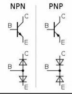
A transistor can be likened to two diodes connected as shown here, at least for basic checks.
A silicon diode can not drop more than about 0.6 to 0.8 volts when forward biased.
You can see the NPN and PNP equivalents here and how your big volt drop across the B-E junction shows a problem. You have shown the base to be the more positive voltage and so we can with certainty that the device or connections/print to it are faulty.
Attachments
the transistor Qe14 is not the original 2SC984, it has been replaced with a KSC2383..also I notice that De3 is a green diode (single) and De2 has been replace with (2) diodes in series from De2 to De4, does this make sense?
It sounds like it has been well a truly got at 😀
I can't actually see a De3 or De4 on the diagram tbh. Are they in series with De1 and De2 and marked on the board but not the circuit diagram.
De1 and De2 are simple bias generators and develop 0.6 volts (or 1.2V if they are a special double diode which does exist) and they are used also for temperature compensation to keep the bias current stable as the amp warms.
So if they were double diodes then yes, two series ones does make sense.
TOMORROW 🙂
Mooly, thanks for all your help, I replaced Qe14 with a KSC2383 I had, and cleaned up the board checking for breaks and dry solder joints. The receiver is up and running with great sound and no distortion. You have helped me out alot and I will put in for you a pay raise🙂🙂 thanks again!
 thanks. Good to hear you have it sorted
 - Home
- Amplifiers
- Solid State
- Kenwood KR-3130