Increasing R1 is likely why there was more noise. This is one application that calls for a more specific circuit.
thanks. just an fyi both of those seem to be end of life also. though I found the 1837 at digikey.
Hello, I followed this thread a long time. Interesting concept. After so many circuits, which one is to choose, which is the final design? On keantoken´s page some details are not shown. The 2SC5171/2SA1930 is still available at the ebay store diy-audio4you, at least here in Germany.
Does anybody have a proper pcb layout from the latest design for my inspiration? I like to make my own to learn these things (Target program)......
Does anybody have a proper pcb layout from the latest design for my inspiration? I like to make my own to learn these things (Target program)......
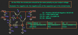
R1 should be 150 for that, otherwise Q2 would never turn on. Also there is a risk of oscillation. I think BC560C will work, but be cautious.
Thank you Kean, now it looks very simple, with maximum effect. Neat!
Does someone have a layout for the pcb, single sided, as a drawing or picture, to learn from?
Does someone have a layout for the pcb, single sided, as a drawing or picture, to learn from?
Last edited:
My boards aren't necessarily good to learn from because of the ground plane.
These boards are flawed, but they may give you an idea.
DirtyPCBs.com
Take note of the patch I described below. The connections on the board are correct, but in the wrong order in such a way that parasitics cause oscillation.
These boards are flawed, but they may give you an idea.
DirtyPCBs.com
Take note of the patch I described below. The connections on the board are correct, but in the wrong order in such a way that parasitics cause oscillation.
They can be made to work if you wire C1 directly from Q1's base to the ground pin of C5, and do the equivalent for the negative side.
I still doubt Rbb is an issue (but if it is we'll figure it out).
Hfe for Q1 and Q3 should be at least 200 or higher preferably. If it is high enough, we can change R2 to 10k for better bass (if that's even necessary)...
- keantoken
Can i do this in the high voltage version ?
Thank you Kean
I am planning to use the high voltage version as ripple killer for the front end of my power amp.
It will feed the IPS and VAS because I am not sure if it can also be used to feed the driver stage.
The IPS plus VAS run at 16mA so I added a shunt resistor in the output of the kmult just to increase current pull to 40mA.... Is there a better way to do it ?
I think that should be fine. For this amp there should be no problem running the drivers from the KM.
I think that should be fine. For this amp there should be no problem running the drivers from the KM.
Thank you Kean
Would you elaborate on this ?
Why, in this amp you state there should be no problem feeding the drivers with the KM ?
Are there any issues if I try to use the KM feeding the drivers of a differnt kind of power amp ? Example, would it be suitable even if the output stage was not made with laterals ?
The drivers are not really loaded by MOSFET gates, so there will not be much current demanded from the KMs. For a BJT output amp the situation could be different.
- Home
- Amplifiers
- Power Supplies
- Keantoken's CFP cap multiplier