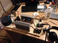
As i stated earlier, i replaced the BC337 this morning. Now both channels measure the same with the exception of the imbalance on one channel. It is small enought that I am proceeding. There is less than 1mV of ripple, so I am assuming all is well in the land of Oz.
I use another KM board for my J-Mo Mk II headphone amplifier.
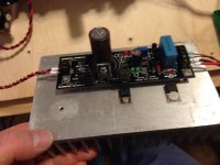
Excellent results!
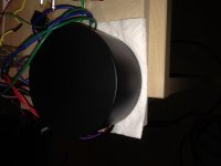
About 2V drop and it is feeding Salas BIB. Very clean power!
Excellent results!
About 2V drop and it is feeding Salas BIB. Very clean power!
Attachments

Sounds good then Buzz, it looks like you are getting the benefits of the Kmultiplier even with the strange result. I would measure ripple again while under load to check if output impedance is okay.
Looks good Alex, I'm glad you like the result.
Looks good Alex, I'm glad you like the result.
Dear keantoken,
you have mentioned a three transistor design with less output impedance, I am very interesting in it. I have probed your design with BD140&BC337 and it works fine without parasitic oscillation, but if I want to have real low output impedance, it needs a lot of current.
Aim of circuit is the analog supply of a WM dac, it sounds better with very low impedance power supply. Have you any measurement data about noise increasing / decreasing? What is your opinion about this?
The BC3x7 is a very low-noise transistor. I don't expect the Kmultiplier to have much more noise than this transistor. The noise will be buried in ripple (~200uV-1mV) unless the input ripple is very low.
I have a 3-transistor version but I haven't tested it yet.
I have a 3-transistor version but I haven't tested it yet.
KMultiplier for Preamp Power Supply
Hi Kean,
I would like to replace my PS Audio Preamp "Power Supply" with KMultiplier.
However I have some question :
1. Can I combine KMultiplier with LM-317 and LM-337 without effect to the
sound performance.
or possible to use trimmer in KMultiplier to adjust output voltage and
make same output voltage between positive section and negative section.
Please suggest your best solution.
Because my transformer 24 VAC, after rectifier and capacitor about 33 VDC.
Preamplifier need about 28 VDC.
2. Recommended Capacitor after output K-Multiplier.
3. What about snubber filter and bladder resistor.
Thank you for your help, I am beginner my question maybe funny.
Rgds,
Sun

Capacitors: I would use plain old Nichicon VR, because it is good and inexpensive. Many here prefer Panasonic FC for many of their projects so you may use that if you want.
Bleeder resistor: I would use a normal 6.8k after the KM for 28V.
Trimming: I suggest to increase R2 for the KM that has higher output voltage.
Snubber filter: What do you mean?
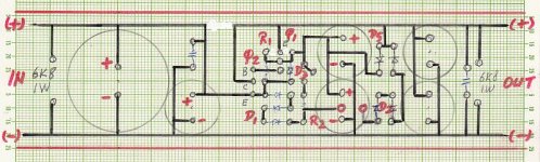
Your schematic will work. There should be at least one lytic near the output of the KM.
Bleeder resistor: I would use a normal 6.8k after the KM for 28V.
Trimming: I suggest to increase R2 for the KM that has higher output voltage.
Snubber filter: What do you mean?
Your schematic will work. There should be at least one lytic near the output of the KM.
Dear Kean,
Thanks and appreciated to your response.
Snubber Filter means C+R (10nF + 10R) after KM.
You mean by increase R2, I not need to use voltage regulator to have 28 VDC of output KM.
Rgds,
Sun
Thanks and appreciated to your response.
Snubber Filter means C+R (10nF + 10R) after KM.
You mean by increase R2, I not need to use voltage regulator to have 28 VDC of output KM.
Rgds,
Sun
I don't know why you would use a 10R+10nF snubber after the KM, there will be no benefit.
Increase R2 only if you want to trim output slightly.
Chip regulators have very large output inductance which will resonate with electrolytics at their output. Some people say this results in bad sound. So it would make sense to try a KM after a chipreg to see if it is an improvement.
Increase R2 only if you want to trim output slightly.
Chip regulators have very large output inductance which will resonate with electrolytics at their output. Some people say this results in bad sound. So it would make sense to try a KM after a chipreg to see if it is an improvement.
Dear Andrew,
I just look at internet and get an idea.
The circuit I copy paste from SupperTeddyReg.
Actually I am mechanical engineer, but funny my hobbies in electronic so my knowledge to limited in electronic.
As per tips of Mr. Kean I decide to use KM only without combine with SupperTeddy voltage regulator.
Thanks to your response of the schematic my knowledge add.
I you have any tips to add my knowledge you are wellcome.
Dear Kean,
I just to make sure if 10R+10nF snubber needed, since you are not recommended so I not use it.
May I series R2 (1K) with trimmer 2K.
Last quotestion.
I would like to build two positive regulator instead of positive regulator and negative regulator.
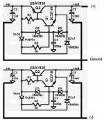
It is OK for KM with two positive regulator as per schematic below.
Rgds,
Sun
I just look at internet and get an idea.
The circuit I copy paste from SupperTeddyReg.
Actually I am mechanical engineer, but funny my hobbies in electronic so my knowledge to limited in electronic.
As per tips of Mr. Kean I decide to use KM only without combine with SupperTeddy voltage regulator.
Thanks to your response of the schematic my knowledge add.
I you have any tips to add my knowledge you are wellcome.
Dear Kean,
I just to make sure if 10R+10nF snubber needed, since you are not recommended so I not use it.
May I series R2 (1K) with trimmer 2K.
Last quotestion.
I would like to build two positive regulator instead of positive regulator and negative regulator.
It is OK for KM with two positive regulator as per schematic below.
Rgds,
Sun
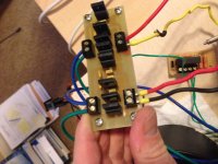
Attachments
Looks good to me.
The trimmer will only work to trim voltage within 100mV or so. At any rate I don't think a rail voltage mismatch of a few hundred mV will make a difference in the behavior of most circuits.
The trimmer will only work to trim voltage within 100mV or so. At any rate I don't think a rail voltage mismatch of a few hundred mV will make a difference in the behavior of most circuits.
The 6.8k only needs to be 250mW for 28V.
R1 is connected wrong, it should go to the Q1 collector instead of base.
R1 is connected wrong, it should go to the Q1 collector instead of base.
Last edited:
Hi,
Just to let you know that 4 KM printed circuit boards (PCBs) have been sold. There are only two left. If you want one, please get in first before they are sold out.
I won't have these boards made any more because the batch I had was for 4 KMs used in my own system. All proceeds will go to Keantoken for his R&D work.
Regards,
Bill
- Home
- Amplifiers
- Power Supplies
- Keantoken's CFP cap multiplier