Yes, there is no point in using a kmultiplier between the shunt and the load.
It would be totally counterproductive..... we made a lot of work lowering the shunt output imp and making it stable with a film cap in the output .... in one of my best builds I even eliminated local decoupling caps in the input amp, getting much faster and detailed sound.... why would we strangle all that using a large cap (k mult) in between ?
It would be totally counterproductive..... we made a lot of work lowering the shunt output imp and making it stable with a film cap in the output .... in one of my best builds I even eliminated local decoupling caps in the input amp, getting much faster and detailed sound.... why would we strangle all that using a large cap (k mult) in between ?
That makes sense.🙂
I was a tester for the Salas shunt reg a while ago. Can you point me to the latest schematic, i.e. a link to the latest schematic / post number in the thread?
I was a tester for the Salas shunt reg a while ago. Can you point me to the latest schematic, i.e. a link to the latest schematic / post number in the thread?
Last edited:
This sounds wonky !.......... .... in one of my best builds I even eliminated local decoupling caps in the input amp,...........
And this confirms the sound is wonky !getting much faster and detailed sound....
Andrew, it could be that removing the local decoupling also removed a resonance, and because of this the circuit works better despite the increased supply inductance. These things are not always straightforward. Of course you could be right. It would take some investigation to see exactly what effect RC's changes had on the rail behavior.
This sounds wonky !And this confirms the sound is wonky !
Hi Andrew.... 🙂🙂🙂
What do you mean by wonky ? Do you mean I am having a pleasurable listening session with un unstable system ?
Andrew is referring to the phenomenon that a misbehaving system may cause distortions that are pleasing and/or cause the illusion of more accurate sound. IE "fake Hi-Fi". We cannot however know if this is really the case or not, because we have almost no information.
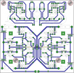
Could someone put eyes on this layout abd see if you spot a problem. I started to solder in the wires from the prereg and the little amount of juice left in the caps exposed what appears to be a short. I cannot find it on the board or the layout, but perhaps I am looking to hard.
Attachments
Filling up 2000uF might be enough to make a spark, depending on the voltage. Can you measure a short with the ohm meter?
The output caps do not fill immediately when you apply power. They ramp up too slowly to cause a spark. I don't think the spark in itself would indicate a short.
Maybe something got hidden under the caps when soldering and is causing a short? I had that problem when I got a board wet. The water caused a bridge to form through electrolysis.
Maybe something got hidden under the caps when soldering and is causing a short? I had that problem when I got a board wet. The water caused a bridge to form through electrolysis.
Coldnt find anything, so ifired it p with reckless abandon. All seems fine, although i would have thought the LED would stay on. It lights up that turns off.
Interesting problem popped up. Not sure how to figure what needs replacing. My positive rail has dropped about 5V. It is the same whether it is loaded or unloaded. The input voltage is correct. Which element have I lost. I will begin probing in anticipation.
For some reason it seems too much current is being drawn through R2. This could be Q2 going open, Q1 damaged through reverse discharge, R1 shorted, C1 becoming leaky, in rough order of probability.
Is there any load? The voltages won't be right if it's not loaded during testing. Can you measure the voltage across all transistor junctions and post?
- Home
- Amplifiers
- Power Supplies
- Keantoken's CFP cap multiplier