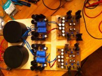
So, Q1 is not turning on for some reason. Is R2 or the diode string open? Do you have caps next to the input and output?
http://www.diyaudio.com/forums/powe...tokens-cfp-cap-multiplier-67.html#post3913845
Here it is. I have had no issue with the other psu or the negative rail. I can check again, but the diodes tested ok.
Here it is. I have had no issue with the other psu or the negative rail. I can check again, but the diodes tested ok.
Here is another odd thing. The total voltages of the positive and neg rail sum to the proper total amount. It is as if their is an imbalance and ground point has shifted towards the positive rail more than the negative rail. I do not create a star ground point until the main board. That is where they are tied together. Is there something that could be causing an imbalance and shift theis mid point to favor one side over another.
There is no reason the Vbe of Q1 should be 4V. 4V will blow any rectifier, so unless there is a connection problem, Q1 is gone for sure.
Does your trafo have a center tap and is it connected to ground?
Does your trafo have a center tap and is it connected to ground?
Q1 was replaced and offset improved slightly. I have dual secondaries running through dual graetz, and each rail is floating until it is joined at the main board. It is a dual mono setup. Both multipliers have equal input voltages. The one channel is equal post multiplier. The other shows an imbalance.
Little update. On the good channel, I have a Vbe of .647V. Same for bad channel. On good channel, I have Vbc of 1.3+V, on the bad channel, I have 2.6+V.
Use the diode tester and test the diode string. Also check the resistors. Maybe you used a 4.7R instead of 47R?
4148's test @.62V on both channels.
1n400x test @.58V on both channels.
47r measures 38.7r in circuit.
1n400x test @.58V on both channels.
47r measures 38.7r in circuit.
I will measure tonight. What are you interested in. Oddly enough, I changed the BC337 and the rails got a little closer. I am swondering if there are transistor parameters that are saffecting the outcome. The small BJt's came on a tape and I have always found that these tend to measure failry close when traced, but perhaps not. Is it reasonable to think a significant parameter difference could cause the change. My rails now only show a difference of about 1V, but still show an imbalance. I guess i could replace the diodes and see if that resolves the remaining difference. I am more interested in knowing what went wrong or what changed?
As long as Q1 has more than 750mV Vbe, the circuit is broken.
Measure the one you pulled out with a diode meter, and why not Hfe if your meter has it.
Measure the one you pulled out with a diode meter, and why not Hfe if your meter has it.
OH.
Vcb reading 2.6V is definitely not right. Can you measure ripple across C1 and the output for both KMs, using an AC voltmeter with twisted leads? It should read less than 1mV. Short the leads before you measure to check the noise floor of the meter.
Vcb reading 2.6V is definitely not right. Can you measure ripple across C1 and the output for both KMs, using an AC voltmeter with twisted leads? It should read less than 1mV. Short the leads before you measure to check the noise floor of the meter.
The ultimate test of whether it's working is whether the ripple is below 1mV. I'm not sure either one is working correctly. Oscillation seems like a potential culprit here, and if so, then it could be counterfeit transistors (where did you get them?) or perhaps the long trace from the first lytic to the KM input. I haven't had that problem yet though.
- Home
- Amplifiers
- Power Supplies
- Keantoken's CFP cap multiplier
