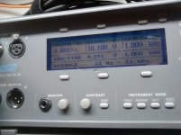
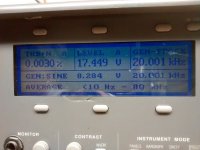
Today I brought in an Audio Precision Portable One Plus. Not the bleeding edge nowadays, it was built in the 90ties. Nonetheless its generator output delivers upto 30V output level with less noise than my sound card. So I fed the amp using the AP while recording the spectrum with my soundcard at 18Vrms output into 10R - just below clipping comes in.
Attachments
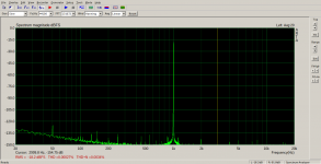
It is a pity the AP does not offer bare THD but only THD+N. The result is 0.001% being 3times below the readout of the soundcard. This confirms lower noise of the AP - anyway THD measurements are at their limit as well.
Is it the AP display you are referring to? There is a problem with the backlight as well.You are having a blast I can see
BTW You can't measure noise floor from a power spectrum plot, you need the power spectral density plot for that, because noise depends on bandwidth and you have to correct to unit bandwidth and correct for the window function noise-bandwidth.
I am aware of that. What I did is comparing both noise floors with the same setup of FFT bins. And the observation that there is more noise with the soundcard than with the AP is backed up by the THD+N numbers imho.
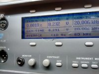
The display is faint, i.e. backlight is dim. So I looked for the backlight supply inside the AP. A small 60Hz xformer delivers approx 150Vac, so I think this is ok. Or have these LCD from the nineties all been that faint and I have simply forgotten the old ones?
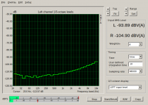
The 50Hz peak discovered by noise measurement (posting #113) gave me some headache. Any screening, grounding or ground lifting did not impress it at all - looked like a nature constant. Inacceptable!😡
If it were 100Hz, I would check the power supply - but 50Hz? At the very end it was the power supply, that is the charge pumps that add some 12V to the driver supply voltage. These produce a 50Hz sawtooth ripple and increasing filter caps on the pos supply showed immediate achievements in hum reduction.
I guess that due to the limited impedance of the input stage pnp current source is slightly current modulated by the pos supply ripple. This small ripple current flows through the differential pair and is not perfectly cancelled due to real imbalances of the circuitry. The measured supply ripple of 1.6Vpp (ca0.5Vrms) produced about 15uVrms output noise corresponding to 90dB PSSR at 33x voltage gain or 120dB referred to input. Not bad at all, but by increasing the filter caps from 220u to 1500u and decoupling resistors from 10R to 100R this peak disappears entirely and no longer annoys the eyes.
Attachments
Last edited:
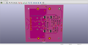
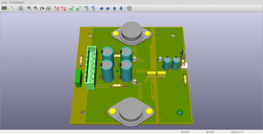
This is the actual rectifier module:
Have you tried to put simple RC snubbers across the transformer wingdings?
also the 22 uF capacitors may not be sufficient, the ripple will increase when loaded, or even the diference between the driver and output power supply ripple is what you are seeing in your measurements.😉
I did not try any RC snubbers across the windings. For my knowledge these dampen hi-frequency resonant oscillations of the secondary windings but do not affect 50Hz.Have you tried to put simple RC snubbers across the transformer wingdings?
also the 22 uF capacitors may not be sufficient, the ripple will increase when loaded, or even the diference between the driver and output power supply ripple is what you are seeing in your measurements.😉
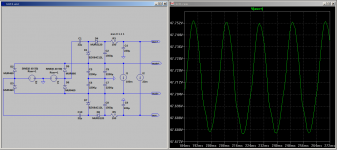
The 22uF are the charge pump coupling caps. They are some kind of ac current source that feed the drivers only with their constant current consumption of approx 23mA. So there is no point in increasing them above that value. Feel free to play around with the asc-file!
Last edited:
While mains is 50/60Hz mains noise can be any frequency/frequencies.I did not try any RC snubbers across the windings. For my knowledge these dampen hi-frequnency resonant oscillations but do not affect
One of my early designs blew up when my fridge motor turned off.
The spike on the mains from the motor got through the transformer and spiked the DC supplies killing an output transistor.
So either snubber the transformer or put local 100uf/100nf caps on each rail close to the amp.
The problem with your AC pumping circuit is that is a half wave rectifier over a full wave rectifier signal, there is a diferential AC waveform in between those supplies that worsen when loaded.😀
Last edited:
While mains is 50/60Hz mains noise can be any frequency/frequencies.
One of my early designs blew up when my fridge motor turned off.
The spike on the mains from the motor got through the transformer and spiked the DC supplies killing an output transistor.
So either snubber the transformer or put local 100uf/100nf caps
on each rail close to the amp.
The question here is whether you have to deal with common mode or differential mode noise. Common mode noise is hardly understood by DIYers and may disturb the circuits depending on their physical layout. RC-snubbers may or may not help here.
To prevent CM noise from disturbing the circuit the secondary is connected to PE and, more important, sensible tracks of the pcb are as short as possible to reduce capacitive coupling paths against earth. Furthermore they are sreened by a copper plane.
Differential mode noise is blocked by the rectifier bulk caps as the first instance.
And additionally by local caps on the pcb - lowest ESR polymer caps 220uF are blocking the rails near the power MOSFETs.
Last edited:
So what exactly is the problem?The problem with your AC pumping circuit is that is a half wave rectifier over a full wave rectifier signal, there is a diferential AC waveform in between those supplies that worsen when loaded.😀
Last edited:
- Home
- Amplifiers
- Solid State
- Just another lateral FET amp