PMA said:
No. It has pure 3rd harmonic of some 1%, so it is NOT perfectly linear. 3rd harmonic is NONLINEAR distortion.
Yes, I stand corrected. Got carried away 😡
Jan Didden
Where does the 3'rd harmonic come from a simple differential pair? I am not talking about someone's compromised circuit, just a simple differential pair. It has to have some 3'rd harmonic, however 2'd harmonic is an artifact of circuit imperfection in some way. Perhaps matching, thermal offset, etc.
grid
Hi Pavel,
If you adjust the grid spacing of your harm graph it'll look much cleaner. Specify 10k,1k,1k in the X-range column, for example.
Not 10k,1k,100 or something like that.
Regards, Edmond.
Hi Pavel,
If you adjust the grid spacing of your harm graph it'll look much cleaner. Specify 10k,1k,1k in the X-range column, for example.
Not 10k,1k,100 or something like that.
Regards, Edmond.
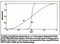
john curl said:Where does the third harmonic come from in a differential pair? Why doesn't someone do something useful and show us.
Come on John, symetrical compressive non-linearity is all odds.
Think of squashing the top and bottom of a sine wave symetrically until it becomes a square wave.
I know you realize that. 🙂
It is only a question of scale (or FFT BW), with higher resolution there are always both odd and even harmonics, that were probably hidden in noise in older measurements. Real device transfer function is not ideal.
Re: grid
I believe we all are matured. Voltage 10x = 20dB. -40dB (100X) = 1% distortion, -60dB (1000x) = 0.1% etc.
Edmond Stuart said:Hi Pavel,
If you adjust the grid spacing of your harm graph it'll look much cleaner. Specify 10k,1k,1k in the X-range column, for example.
Not 10k,1k,100 or something like that.
Regards, Edmond.
I believe we all are matured. Voltage 10x = 20dB. -40dB (100X) = 1% distortion, -60dB (1000x) = 0.1% etc.
Scott, anyone can do it graphically, but can you do it mathematically?
Why is it when two components, presumed to have only second harmonic, when differentially put in series together, create 3'rd harmonic in surprisingly large amounts?
Why is it when two components, presumed to have only second harmonic, when differentially put in series together, create 3'rd harmonic in surprisingly large amounts?
You must be teasing us 😀 . How about difference between transfer function of single device and LTP pair?
Re: Re: grid
Hi Pavel, I'm talking about the X-range (NOT y-range) and how to get rid of those (highly annoying) zillions of grid lines (see below)
PMA said:I believe we all are matured. Voltage 10x = 20dB. -40dB (100X) = 1% distortion, -60dB (1000x) = 0.1% etc.
Hi Pavel, I'm talking about the X-range (NOT y-range) and how to get rid of those (highly annoying) zillions of grid lines (see below)
Attachments
john curl said:Want to break it down? You know, derive it?
John,
http://rfic.eecs.berkeley.edu/~niknejad/ee142/pdf/lect7.pdf
I hope this is what you are looking for, any further questions?
john curl said:Scott, anyone can do it graphically, but can you do it mathematically?
Let's see it for FET's, closed form now, no cheating. The Taylor series expansion for long tailed pairs has been published ad nauseum. From Walt's graph there I'd guess we would start with AX - BX**3 and go from there. This is sort of intuitive stuff, take a square law non-linearity and flip it on the other side of the axis and take the Taylor series. And please, I don't mean to insult anyone who has to think about it for a while, that's what learning is all about.
Procedure of math derivation is well illustrated in the link that syn08 gave here, thanks, Ovidiu.
Here's my point.
It has previously stated or at least implied in this forum that
degeneration as local feedback creates higher order harmonics
that did not exist in the undegenerated state.
A little thought experiment convinced me that this cannot be
generally true. We know that the harmonic content of the
amplified output reflects variations in gain due to the fluctuations
of current through the device and also voltage across the device.
So consider the example a JFET operated Common Source. We
can freeze the Vds by cascoding it and measure the distortion
for a given output current swing. When we compare the
harmonics for the undegenerated case with the degenerated
case (Source resistor), we see that the distortion remains the
same for the same current swing. In the degenerated case of
course, the input voltage is much higher, and the distortion is
lower by comparison to it, but the ratio of the harmonics remains
the same.
Not content with that, I built up the circuit which performed this
experiment and measured the distortion and its spectral content
and confirmed that this was the case to reasonable accuracy.
I also noted that if I did not hold the Vds constant, but let it
alter out-of-phase with the input signal, there was suppression
of 2nd harmonic and an increase in 3rd. This latter was true for
both Common Source and Common Drain examples, but if you
think about it, this voltage variation acts more or less like loop
feedback, and simply confirms what we already know about
negative feedback loops.
I have to conclude that there is in fact a real distinction between
the performance degenerative local feedback and loop feedback.
Nelson Pass said:Here's my point.
It has previously stated or at least implied in this forum that
degeneration as local feedback creates higher order harmonics
that did not exist in the undegenerated state.
Baxandall and Cherry were only talking about global feedback I think, as was I, sorry for any misunderstanding. Baxandall IIRC only presented measurements (and shunned too much math) on a real JFET amplifier which did show the effect. I'm sure Cherry did somewhat the opposite.
I certainly was not referring to any comments from you, Scott,
or anyone else in particular. The subject is an older one from the
"Cordell on Negative Feedback" thread, and I simply could not
resist adding my own two cents.
😎
or anyone else in particular. The subject is an older one from the
"Cordell on Negative Feedback" thread, and I simply could not
resist adding my own two cents.
😎
- Status
- Not open for further replies.
- Home
- Amplifiers
- Solid State
- John Curl's Blowtorch preamplifier