He's not looking for tanh. Which, is derived by the law of the junction and the identity tanh(x) = (e^x - e^-x )/(e^x + e^-x).
Thanks syn8, but it is not complete enough to include differential fets, however I did take 142 in 1971 with Don Pederson (father of SPICE) at UCB and I have the class notes around here somewhere. Also, 242 notes. Do you have those as well?
Nelson Pass said:We can freeze the Vds by cascoding it and measure the distortion
for a given output current swing. When we compare the
harmonics for the undegenerated case with the degenerated
case (Source resistor), we see that the distortion remains the
same for the same current swing.
How so?
In the un-degenerated case, the AC component of Vgs(t) is constrained to be an undistorted sinusoid. In the degenerated and global feedback cases, there is no such constraint. With very high degeneration or global feedback, Vgs(t) will be distorted in such a way as to reduce the distortion of the output current to a level below that which would be obtained with a purely sinusoidal Vgs(t).
fizzard said:He's not looking for tanh. Which, is derived by the law of the junction and the identity tanh(x) = (e^x - e^-x )/(e^x + e^-x).
Tanh is for BJT.
There is no special difference between local and global feedback, regarding their effect on non-linearity. The feedback is distinguished as voltage, current, parallel and series.
However, nowhere, no-how, can I find the exact expression for an ideal (or non-ideal) FET differential pair. The analysis just stops in the texts, and I was hoping that someone would have it handy and would put it here, so we could discuss it.
Now why would I like to discuss this example, when the bipolar example is there for the taking?
Well, ideal FET's don't have any 3rd harmonic when used without local feedback and single ended. WHY do ideal FETS have 3'rd harmonic (mathematically, not graphically), and where does it come from? Let's show exact equations, not guesses. Then we can solve Nelson's questions and learn something new.
andy_c said:In the un-degenerated case, the AC component of Vgs(t) is constrained to be an undistorted sinusoid. In the degenerated and global feedback cases, there is no such constraint. With very high degeneration or global feedback, Vgs(t) will be distorted in such a way as to reduce the distortion of the output current to a level below that which would be obtained with a purely sinusoidal Vgs(t).
Well, you're quite right that the constraint has changed to that of
Vgs to Vgs plus the voltage across the Source resistor. I suggest
that you try simulating the circuit I described, and see what you
get. As I said, I built one and did not observe the creation of
higher order harmonics or a significant difference in the relative
amplitudes on the pre-existing harmonics.
Really good point you make, by the way.
Guys, if I understand correctly the contention, both approaches below are perfectly equivalent.
a) The degeneration resistor drops voltage proportional to the emitter current through the transistor. The voltage drop is opposing the input signal's effect on the BE junction. With no degeneration, Vbe variation equals the Vi variation. With a degeneration resistor R the voltage dropped across the resistor adds with Vbe to equal Vi. As a result Vbe will no longer be equal to Vi. R will drop a voltage proportional to emitter current, which is in turn controlled by the base current. The base current is in turn controlled by Vbe. Thus, if Vi were to increase in a positive direction, it would increase Vbe, resulting in more base current, causing more emitter current, and as a result of all this more voltage to be dropped across R. This increase of voltage drop across the degeneration resistor subtracts from Vi and reduces Vbe, so that the actual voltage increase for Vbe will be less than the voltage increase of Vi. Consequently, the input voltage has less control over the transistor than before, and the voltage gain for the amp is reduced. To put it in another way, R reduces the interval in which changes can occur on the exponential function. The same input change from without degeneration results in a smaller change of Vbe. As a result we will be working in a smaller part of the exponential function which results in less non-linearity.
Complicated, and not very analytical, isn't it?
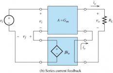
b) It's much simpler if you look at degeneration as [local] series (input) current (output) NFB. The base amp gain is transconductance and the equivalent circuit is shown in the attachment. You would of course recognize the qualitative model above (voltage drop that oposes Vi, yada-yada-yada) but now we can directly write the amp gain as a function of the gain loop, etc... as in http://www.ece.mtu.edu/faculty/goel/EE-4232/Feedback.pdf
John:
JFETs are sometimes used in the belief that these produce only second harmonic while BJTs generate higher order components. A perfect square law fet alone will generate only second harmonic distortion, however, real devices and their mismatches in a differential pair will create 3rd (see Baxandall measurements and this analytic discussion http://www.its.caltech.edu/~musiclab/feedback-paper-acrobat.pdf ).
No, I haven't studied at UCB - but I have myself, somewhere in the basement, plenty of notes from those times 🙂
a) The degeneration resistor drops voltage proportional to the emitter current through the transistor. The voltage drop is opposing the input signal's effect on the BE junction. With no degeneration, Vbe variation equals the Vi variation. With a degeneration resistor R the voltage dropped across the resistor adds with Vbe to equal Vi. As a result Vbe will no longer be equal to Vi. R will drop a voltage proportional to emitter current, which is in turn controlled by the base current. The base current is in turn controlled by Vbe. Thus, if Vi were to increase in a positive direction, it would increase Vbe, resulting in more base current, causing more emitter current, and as a result of all this more voltage to be dropped across R. This increase of voltage drop across the degeneration resistor subtracts from Vi and reduces Vbe, so that the actual voltage increase for Vbe will be less than the voltage increase of Vi. Consequently, the input voltage has less control over the transistor than before, and the voltage gain for the amp is reduced. To put it in another way, R reduces the interval in which changes can occur on the exponential function. The same input change from without degeneration results in a smaller change of Vbe. As a result we will be working in a smaller part of the exponential function which results in less non-linearity.
Complicated, and not very analytical, isn't it?
b) It's much simpler if you look at degeneration as [local] series (input) current (output) NFB. The base amp gain is transconductance and the equivalent circuit is shown in the attachment. You would of course recognize the qualitative model above (voltage drop that oposes Vi, yada-yada-yada) but now we can directly write the amp gain as a function of the gain loop, etc... as in http://www.ece.mtu.edu/faculty/goel/EE-4232/Feedback.pdf
John:
JFETs are sometimes used in the belief that these produce only second harmonic while BJTs generate higher order components. A perfect square law fet alone will generate only second harmonic distortion, however, real devices and their mismatches in a differential pair will create 3rd (see Baxandall measurements and this analytic discussion http://www.its.caltech.edu/~musiclab/feedback-paper-acrobat.pdf ).
No, I haven't studied at UCB - but I have myself, somewhere in the basement, plenty of notes from those times 🙂
Attachments
john curl said:However, nowhere, no-how, can I find the exact expression for an ideal (or non-ideal) FET differential pair. The analysis just stops in the texts, and I was hoping that someone would have it handy and would put it here, so we could discuss it.
That's probably because the result never interested Barrie Gilbert
🙂 also the IEEE seems to not allow search engines to find key words in their archives. I don't see why, they might sell more downloads of the complete papers.
Like TANH the transfer function of a long tailed FET pair HAS to be expressed as A + Bx**3 + Cx**5.... because it is a symetric odd function. The coefficients will be a function of Idss, Vp, and Ibias. This IS math and not graphs, the exact coefficients might be interesting or not. I have found that one cannot come up with any magic degeneration or arrangement that flattens the transfer function around zero like a bipolar. It is possible an exact solution requires some esoteric transformation of variables or maybe Volterra techniques. I do know that no one I have run into ever found the exact answer interesting.
There is no mystery or magic and no non-idealities are necessary. A long tailed pair of anything creates and i1-i2 function that is symetric and odd.
scott wurcer said:That's probably because the result never interested Barrie Gilbert
🙂 also the IEEE seems to not allow search engines to find key words in their archives. I don't see why, they might sell more downloads of the complete papers.
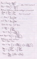
I'm part way there. Can somebody check my math? Here is page 1.
Attachments
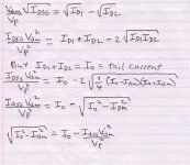
You're on the right track, these days I would use a crutch like Mathcad or Matlab to do explicit symbolic answers. They don't miss those factors of two or the square root of PI.
john curl said:Nelson, we are doing this for you and me. Stick with the program!
Hi John,
I'll finish this up tomorrow. I got a new pair of speakers yesterday, so I'm doing a marathon listening session at the moment 🙂
scott wurcer said:
There is no mystery or magic and no non-idealities are necessary. A long tailed pair of anything creates and i1-i2 function that is symetric and odd.
Exactly. That is what I had in mind when I spoke about difference between trasnsfer function of a single device and a long tailed pair.
I have not expected to say anything new. You were asking about 3rd in a long-tailed pair, and argued with 2nd in a single device.
- Status
- Not open for further replies.
- Home
- Amplifiers
- Solid State
- John Curl's Blowtorch preamplifier