I'm certainly no solid state expert, but it strikes me that there's not going to be an exact equation for FETs. Unlike bipolars, their characteristics are not determined by basic physics (e.g., Ebers-Moll), but by device geometries- much like tubes in that respect. So one can't universalize an exact equation there any more so than one can the same for tubes- yes, it's basically square-law, much like a tube is 3/2 law, but not exactly and won't be exactly the same for any two different devices.
If I'm completely wrong here, I assume Scott will gently slap me around a bit and make me smarter.
If I'm completely wrong here, I assume Scott will gently slap me around a bit and make me smarter.
Nelson Pass said:Let me guess. The answer is 42.
😎
Nelson,
On your 'thought experiment' and later measurements on the degenerated vs non-degenerated case, at which node did you measure the distortion? On the drain? Was there a current source load in both cases?
Jan Didden
john curl said:I want exact equations, not hand waving. Then we can discuss it.
Transfer function resulting from symmetry of any non-linear functions must in principle introduce odd order harmonic distortion; no so-called exact, in fact quasi-exact equations are needed.
True diffpair see image, only odd.
Attachments
Nelson Pass said:Let me guess. The answer is 42.
😎
Attachments

andy_c said:I am still not finished, but it looks like the last equation on page 2 below can be squared on both sides, then solved for Idm in terms of Vdm. Does this look right so far?
I can’t think of anything particularly intelligent to add to this discussion at the moment, but it reminded me of this – which commonsense tells me I shouldn’t post because it’s in rather bad taste, but my stupid male gene overrides that. 😀 😀
Attachments
SY said:I'm certainly no solid state expert, but it strikes me that there's not going to be an exact equation for FETs. Unlike bipolars, their characteristics are not determined by basic physics (e.g., Ebers-Moll), but by device geometries- much like tubes in that respect. So one can't universalize an exact equation there any more so than one can the same for tubes- yes, it's basically square-law, much like a tube is 3/2 law, but not exactly and won't be exactly the same for any two different devices.
If I'm completely wrong here, I assume Scott will gently slap me around a bit and make me smarter.
Right, bipolars are nice log computing devices that are scale independent. John's being a little needlessly thick here. I'm sure y = x**1/2 x>0 and y=-(-x)**1/2 x<0 has some sort of series approximation and it HAS to only contain odd powers.
janneman said:On your 'thought experiment' and later measurements on the degenerated vs non-degenerated case, at which node did you measure the distortion? On the drain? Was there a current source load in both cases?
Of course I can't find my notes when I need them.
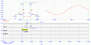
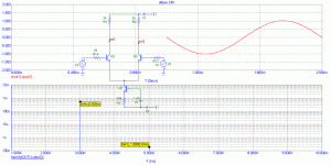
The load was a resistor going from the Drain of a cascode to the
positive supply. The measurements were at a constant output
voltage (I forget the exact values, probably about 1Kohm and
1 Vrms) taken off the Drain of the cascode. As I recall, I kept the
Vds of the gain device at 10V and Ids at the Idss of the device,
which was 8-10 mA. Both devices were 2SK370, and the gain
difference between the raw and degenerated case was about
10 dB, created with a Source resistor to ground. The distortion
was measured by an AP1 and fed to a PC based spectrum analyzer.
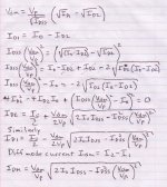
Okay, forget my page 2 in post 3753  . By stealing a technique I found in the analysis of a CMOS diff amp, I found a way to get a closed-form expression for the difference mode current Idm in terms of the difference mode voltage Vdm and the FET parameters. This technique avoids splitting the function into regions, which would have happened had I continued with my previous approach. In solving the quadratic equations for ID1 and ID2, I left out some messy algebra. Basically, what happens inside the radical is you end up with the difference of two squares a2 - b2. You then factor this into (a + b)*(a - b). This trick allows bringing the term involving Vdm outside the radical, which then allows exposing the difference mode current expression as an odd function.
Here's the completed analysis. My original page 1 is okay.
. By stealing a technique I found in the analysis of a CMOS diff amp, I found a way to get a closed-form expression for the difference mode current Idm in terms of the difference mode voltage Vdm and the FET parameters. This technique avoids splitting the function into regions, which would have happened had I continued with my previous approach. In solving the quadratic equations for ID1 and ID2, I left out some messy algebra. Basically, what happens inside the radical is you end up with the difference of two squares a2 - b2. You then factor this into (a + b)*(a - b). This trick allows bringing the term involving Vdm outside the radical, which then allows exposing the difference mode current expression as an odd function.Here's the completed analysis. My original page 1 is okay.
Attachments
Thank you Andy, we seem to have gotten this far. Now we have to convert it, (if possible) to harmonic distortion prediction. I will look at my 241 class notes and Pederson's book and see if I can help in this matter. There are already examples shown (in the book) of single bjt's, fet's (ideal) and differential bjt's, but NOT differential fet's. My math is awfully rusty, but you appear to have done a good job.
What PMA has measured is what we would expect from a calculated measurement.
What PMA has measured is what we would expect from a calculated measurement.
Distortion depends on amplitude, as everyone here knows, rises for higher Vout, but remains in odd components only, for true diff pair (diff in, diff out).
Generalizations are obvious. I want specific equations, so that we can compare the bipolar diff pair to the fet diff pair in terms of 3'rd (or more) harmonic distortion.
It now appears that the answer to my complete question is shown on p. 30 of Pederson's book.
The answer appears to be:
HD3 = 1/32[V)/(Vgg-Vt)]squared or (1/16)(a/Iss)V(squared)
V in this example is the 0-peak voltage of the input AC waveform, so we will have to convert to rms at some point to make it match what we usually measure, but it should be OK for comparison.
where (for example) V is .2V, Vt is 1V, and a= .15A/V(squared), and Iss =1ma then
HD3 = .0375%
Looks like Andy's derivations is fine, it's very similar to the expression I find in the german standard textbook (Tietze/Schenk). Somewhat differently expressed (in terms of transconductance coefficient K instead of pinch-off voltage Vp) but the core transfer is identical, f(x)=ax*sqrt(b - cx^2).
- Klaus
- Klaus
While the taylor series for tanh is easy to obtain (just can be looked up), the series expansion of the FET diff transfer is another matter (not trivial, at least for me). And then you need to use the (recursive) trigonometric identies for the odd powers to get the actual harmonics distribution, which you surely would like to have including all orders up to 7th or 9th. Now who is/knows a math professor (may in a PC format ;-) to solve this? Also for the degenerated case? With more real life FET transfer charactistics than the idealized square law?john curl said:I want specific equations, so that we can compare the bipolar diff pair to the fet diff pair in terms of 3'rd (or more) harmonic distortion.
Maybe simming or building/measuring it is the quicker/easier approach....
- Klaus
KSTR said:While the taylor series for tanh is easy to obtain (just can be looked up), the series expansion of the FET diff transfer is another matter (not trivial, at least for me). And then you need to use the (recursive) trigonometric identies for the odd powers to get the actual harmonics distribution, which you surely would like to have including all orders up to 7th or 9th. Now who is/knows a math professor (may in a PC format ;-) to solve this? Also for the degenerated case? With more real life FET transfer charactistics john all along I thought you than the idealized square law?
Maybe simming or building/measuring it is the quicker/easier approach....
- Klaus
Looks good so far, like the y = x - sqrt(x) example you have to force the oddness by having a rule for +x and -x so you don't have a nice differentiable function, No problem pick a range for Vin (yes the THD depends on level) and apply Fourier decomposition. That is explicit Fourier integrals at odd harmonics. A symbolic loop in Maple should do it in a flash.
John, all along I thought you talking about the fact that a single ended bipolar was an exponential and therefore had evens and odds already (and the evens were cancelled). This actually has nothing to do directly with the spectral content of a diff pair transfer function.
john curl said:Let's stick to 3'rd at first. (this is like herding cats, you know like: class, CLASS!)
I think Dave Fullagar first showed that crosscoupled bi-polar diff pairs with an area ratio of about 4 (Barrie Gilbert derived the exact area ratio) has identically ZERO third order distortion over a small but useful range. Unfortunately discrete designers can't readily make use of that.
- Status
- Not open for further replies.
- Home
- Amplifiers
- Solid State
- John Curl's Blowtorch preamplifier