What the audiohell is that supposed to mean ?Not my way to work.
Don't make the mistake of SYN08 to confuse a charcoal and the final painting exhibited at the Guggenheim museum ;-)
Hans
Not surprised. What about Googleheim ?Yeah, I'm always confused by such complicated names as Guge...Gugh... Gagh...
I don't recall Bruno ever saying it was novel.
Then the circuit is in the public domain and no IP can be claimed or implied.
Ah, I must have misread, I thought the PCB had the copyright on it.
A PCB layout can be, in principle, copyrighted even if the schematic in behind is in the public domain.
He's an artist.What the audiohell is that supposed to mean ?
Hans
It's in Cordell's first edition too. Page 158.
I run some naïve simulations
George
Attachments
Thank you for writing those up, George -- I struggle with translating words into circuits so I couldn't put together what Ed was exactly talking about other than thinking of balanced impedances within a differential amplifier, which wasn't right.
Unfortunately we can't exactly DC offset as result of these sims, but isn't Ed's circuit a form of noise gain?
Unfortunately we can't exactly DC offset as result of these sims, but isn't Ed's circuit a form of noise gain?
Ah, I must have misread, I thought the PCB had the copyright on it.
The usual...
The design presented here is copyrighted, including the schematics, or parts thereof and the PCBs. Use of these for commercial purposes is prohibited without proper written authorization from the authors. For questions regarding copyrights, or general questions regarding this design the authors can be reached at bruno@hypex.nl or ssassen@hardwareanalysis.com. PCBs for this design are available for purchase, please contact ssassen@hardwareanalysis.com for pricing and details.
Copyright does not protect the design anyone can make their own board layout and sell clones with no recourse at all. Patent protection for ideas has been negotiated by international treaty with most nations signing.
George,
Thinking about the new capacitor value, it should be set for a corner frequency based on the DC feedback resistor divided by the gain + 1.
Thanks
ES
Thinking about the new capacitor value, it should be set for a corner frequency based on the DC feedback resistor divided by the gain + 1.
Thanks
ES
A few of the "Oooh, I know electromagnetics!!" contributors here, also chimed in when I built an 8 ohm load resistor out of 28 pieces (56R @ 10W) wirewound resistors.
Building my own noninductive 8R 150W load using wire wound resistors
Apparently I was offline in that time frame.
You did excellent work.
BTW, what is "electro magnetics"...😕😕
😉
Jn
Those 3 are very different, especially the third one. YouTube
You don't know me, don't assume any coincidences in what I'm saying.
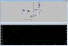
I only hoped to correctly translate your description into a schematic (I have omitted the input dc blocking 5uF capacitor on all circuits).Thanks George,
Now I don't have to look for my copy of Bob Cordell's book. Nice work.
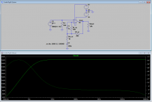
Daniel, again naively, I added an 100mV DC voltage source in series with the AC signal source (and no input dc blocking capacitor). The sim shows DC offset V(vout)dc:Unfortunately we can't exactly DC offset as result of these sims,
Conventional=100.0039mV
Cordel Fig 8-3(a)=100.0137mV
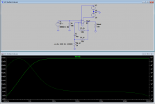
Cordel Fig 8-3(b)=0V
Ed’s idea=100.0099mV
Ed, this I don’t dare to touch. Please translate it into numbers. As you know I am electronics illiterate.Thinking about the new capacitor value, it should be set for a corner frequency based on the DC feedback resistor divided by the gain + 1.
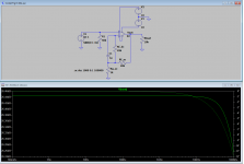
(also the schematic of your idea as I drew it, has 3dB less AC gain than the rest of the circuits. Rf_ac needs to be raised from 20kOhm to 33kOhm for equal AC gain with the rest of the circuits)
George
... To prevent another spitting in it.You blow your own trumpet though 😉
George,
That is because the DC feedback resistor is in parallel with the AC one. So if you use an FET input opamp and raise the DC and non-inverting input resistors to 1,000,000 ohms the problem becomes way smaller.
That is because the DC feedback resistor is in parallel with the AC one. So if you use an FET input opamp and raise the DC and non-inverting input resistors to 1,000,000 ohms the problem becomes way smaller.
Daniel, again naively, I added an 100mV DC voltage source in series with the AC signal source (and no input dc blocking capacitor). The sim shows DC offset V(vout)dc:
Conventional=100.0039mV
Cordel Fig 8-3(a)=100.0137mV
Cordel Fig 8-3(b)=0V
Ed’s idea=100.0099mV
George, much obliged, as always. Some of these are non-intuitive but before anyone else accuses me of needing to go back to EE101 and an idealized opamp model, I think I would do best doing *just* that. Gives a far better grounding for what's going on.
- Status
- Not open for further replies.
- Home
- Member Areas
- The Lounge
- John Curl's Blowtorch preamplifier part III