I think I would do best doing *just* that.

The opamp model in those simulations.
George
Attachments
PGP is a funny name that Syn08 gave to his Amp design.
Blackberry phones equiped with a PGP protocol, standing for Pretty Good Privacy where used by a large Dutch cocaine syndicate, operating internationally,
PGP is an encryption protocol that was supposed to be uncrackable so they could simply communicate with each other.
A long list of shoot and kill victims, among them a solicitor and the son of a Judge. Everybody that came in their way was simply shot.
However, the PGP encryption was finally cracked, leading to a complete insight who were all involved and about the organisational structure.
Right this monday, the Capo di Capi, Ridouan Taghi was arrested in Dubai.
Hans
PGP was developed by Rivest Shamir and Adelman long before that dutch crime syndicate was formed I suspect. If you look up and learn about RSA encryption and the continuing increase with time of minimum recommended key lengths you should be able to work out why they were compromised. Or the Customs officers of some country or another got someone on the inside?
Some of these are non-intuitive
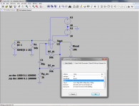
Not really, they can be analyzed by simple inspection. For example the last one in https://www.diyaudio.com/forums/the...wtorch-preamplifier-iii-3239.html#post6014079: LF gain (C is open) is 1 (0dB), HF gain (C is short) is 1+50k||20k/1k~15.3 (23.7dB). Corner frequency is given by 1/(2*PI*C*R) where R is the impedance seen at the C terminals with the independent sources passivized (short voltage sources, open current sources), about 1k (ignore 33k and 50k in parallel) for an ideal opamp, so Fc~4Hz, and it's a sigle LF pole (6dB/octave). Almost exactly what simulation says.
Last edited:
Not exactly.PGP was developed by Rivest Shamir and Adelman long before that dutch crime syndicate was formed I suspect. If you look up and learn about RSA encryption and the continuing increase with time of minimum recommended key lengths you should be able to work out why they were compromised. Or the Customs officers of some country or another got someone on the inside?
PGP can use a number of encryption algorithms to generate its keys. One of those is Rivest–Shamir–Adleman (RSA). RSA is named for its developers, Ron Rivest, Adi Shamir, and Leonard Adleman, who developed the algorithm in 1978.
PGP was developed by Phil Zimmerman and named after the mythical grocery store "Ralph's Pretty Good Grocery" in the mythical town of Lake Wobegon, written and performed by Garrison Keillor.
PGP = Pretty Good Privacy.
It's all on the Wikipedia page
PGP = Pretty Good Privacy.
It's all on the Wikipedia page
Not really, they can be analyzed by simple inspection. For example the last one in https://www.diyaudio.com/forums/the...wtorch-preamplifier-iii-3239.html#post6014079: LF gain (C is open) is 1 (0dB), HF gain (C is short) is 1+50k||20k/1k~15.3 (23.7dB). Corner frequency is given by 1/(2*PI*C*R) where R is the impedance seen at the C terminals with the independent sources passivized (short voltage sources, open current sources), about 1k (ignore 33k and 50k in parallel) for an ideal opamp, so Fc~4Hz, and it's a sigle LF pole (6dB/octave). Almost exactly what simulation says.
Non-intuitive for me, I should be clear. I'm sure I'll slap my forehead the second I draw it out. Circuits aren't my usual thing so I'm a little slow on the inspection. 🙂
More why the Cordell B schematic does null out the DC offset (3rd one). The others made sense, although I hadn't done the RC constants.
More why the Cordell B schematic does null out the DC offset (3rd one). The others made sense, although I hadn't done the RC constants.
#3 cancels out the input bias current contribution to the offset. If an opamp has an input bias current of say 100nA, a 50k resistor on the non inverting input drops 5mV, which multiplied by the closed loop gain (here, 21) gives an output offset of 105mV (which is a lot, while still assumes the voltage offset is zero).
The Rf_dc=49k resistor doesn't affect the gain, since it doesn't drop any AC voltage. So the gain is constant 1+Rf_ac/Rg_ac=21 (26.5dB), independent of frequency.
At DC, C1 is open and the Rf_dc+Rg_ac=50k resistors drop due to the inverting input bias current exactly balances the drop on R1=50k due to the non inverting input bias current. Result: no input bias current contribution to the output offset, output will stay nicely at zero.
It's even simpler than #4, no calculator required 😀.
I shouldn't post this link...
True, you shouldn't. Poorly substantiated claims for a publication. However, you could have chosen a less controversial and less offensive topic to provide a laugh.
You trying to restart the food fights from before?
Last edited:
However, you could have chosen a less controversial and less offensive topic to provide a laugh.
Hardly offensive, but the idea that a proper DBT could take months or years of listening is intriguing. Sort of makes all arguments moot.
Accordingly, the output inductor negatively affects the amplifier sound. An amplifier with an output inductor is compromised.
Double blind? I though it sound same 😀 😀 😀
Richard's Thailand factory already built enough to illustrate. One unstable is one too many.
Mine was stable, but slightly different design.
You can not make a conclusion with only one design. May be the implementation was not good enough.
Richard said his one was stable. Dadod said the one he build for himself too. As oscillations are the first thing we look-at on the bench, why not believe in it ?Mine was stable, but slightly different design.
You can not make a conclusion with only one design. May be the implementation was not good enough.
I made a sim of this amp, and stability margin was blameless.
So, for the moment, the only thing for sure is that SYN08 is just guessing.
Why ? May-be he consider only him is able to design a stable amplifier ?
I cannot believe a respectable EE could be jealous of the talent of an other designer. ;-)
Last edited:
I cannot understand all those controversies about "listenings". When something is obvious, it is obvious and repeatable. And has value only for the listener (Musical culture, personal taste and attention at some details etc.).Hardly offensive, but the idea that a proper DBT could take months or years of listening is intriguing. Sort of makes all arguments moot.
When a difference need hundreds of goings and comings, why bother ?
And if the problem is some peoples believe blind on audiophile reviews, it is their problem. Personally, if I read a very eulogistic review somewhere about some gear, it can give-me the desire to listen to it. And I make myself my opinion (often negative). Not you ?
Blind or not, I don't care (cf: 'obvious') and I will not lose my time and energy to set a complicated installation and protocol for such a stupid subject.
Last edited:
#3 cancels out the input bias current contribution to the offset. If an opamp has an imput bias current of say 100nA, a 50k resistor on the non inverting input drops 5mV, which multiplied by the closed loop gain (here, 21) gives an output offset of 105mV (which is a lot, while still assumes the voltage offset is zero).
The Rf_dc=49k resistor doesn't affect the gain, since it doesn't drop any AC voltage. So the gain is constant 1+Rf_ac/Rg_ac=21 (26.5dB), independent of frequency.
At DC, C1 is open and the Rf_dc+Rg_ac=50k resistors drop due to the inverting input bias current exactly balances the drop on R1=50k due to the non inverting input bias current. Result: no input bias current contribution to the output offset, output will stay nicely at zero.
It's even simpler than #4, no calculator required 😀.
Much obliged. I knew I was missing something.
It is obvious, in a LTP that both + & - inputs need to read the same impedance.Much obliged. I knew I was missing something.
One other advantage of this circuit is that, if you use a coupling cap for the input signal of the same value and kind than the one in the feedback, (and ensure the AC impedance of the source is ~1K), their defects (if any) will be compensated.
Richard said his one was stable. Dadod said the one he build for himself too. As oscillations are the first thing we look-at on the bench, why not believe in it ?
I made a sim of this amp, and stability margin was blameless.
So, for the moment, the only thing for sure is that SYN08 is just guessing.
Why ? May-be he consider only him is able to design a stable amplifier ?
I cannot believe a respectable EE could be jealous of the talent of an other designer. ;-)
🙂🙂 😎 So right on the point, as always. call it like it is.
<3
-Richard
Okay, I want to back the truck up after hand going through things with an idealized opamp. (and then adding things like finite input impedance, bias currents, etc.)
I understand nulling out of the DC offset due to input bias current, that's fine and why I like writing up and solving things by hand at times. (I would have gotten there when I wrote it up)
What I'm hung up on is that *with* 100 mV DC offset placed in series with the AC signal, per George's later notes, the only circuit to zero that out is the Cordell 8-3B circuit. Again, this is nulling out a *differential* 100 mV inherited from upstream. The others show this 100 mV +/- their bias current effects, that one is zero. This circuit is also the only one that has a non-unity DC gain due to configuration. Why doesn't this guy have 21*100 mV = 2.1 V DC offset?
Last edited:
Has anyone considered the effect of these schemes on CM Rejection?
[unequal + and - input Z's as Tryphon said]
THx-RNMarsh
[unequal + and - input Z's as Tryphon said]
THx-RNMarsh
Last edited:
- Status
- Not open for further replies.
- Home
- Member Areas
- The Lounge
- John Curl's Blowtorch preamplifier part III