You just play the same tune, Richard said, not only ones, there was no oscillation.
Maybe, but amplifiers bursting in oscillations and self destructing under difficult loads is unfortunately a very old and familiar tune.
With all due respect, Richard doesn’t have the foggiest idea what he is talking about, as long as he suggested replacing the vertical mosfets with lateral mosfets, just like that.
Tournesol
Opamps PSU must be floating at otput of power stage. Other way it can not work as intended. No, no and no 🙂
Opamps PSU must be floating at otput of power stage. Other way it can not work as intended. No, no and no 🙂
Tournesol
Opamps PSU must be floating at otput of power stage. Other way it can not work as intended. No, no and no 🙂
By challenging a T-E design you have questioned his Klingon family honour. Prepare to die!
A better method is to isolate the AC and DC feedback paths, virtually unknown in the audio world. The DC feedback resistance goes from the output to the inverting input. This value should match the resistance from the non-inverting input to ground used to establish a 0 volt reference. These resistors can usually be a high value such as 100,000 ohms although it is useful to match the input offset current and voltage as before.
Ed, that's discussed in Cordell's book. Figure 10.3 (p.221) of the 2nd edition.
Ed, that's discussed in Cordell's book. Figure 10.3 (p.221) of the 2nd edition.
Only willing to pay for the first one!
I have shown that approach to well regarded folks who were quite confused!
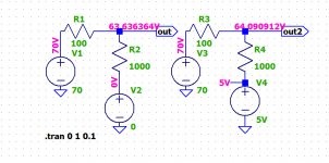
Napoleon said a little schematic says more than thousands words.When correcting a 70 Volt OPS input signal, the correction signal will effectively be in the sub Volt region and should hover around this 70 Volt to correct the input signal.
Suppose input signal is 70 Volt at a certain moment and should be error corrected to 70.5 Volt. This will not be possible with your opamp circuit.
Just the idea. No free lunch, of course, but nothing impossible with a spirit of sacrifice ;-).
Attachments
Last edited:
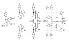
If you search for the Putzeys designed 30W (balanced) class A amp, (Extreme A from memory?) , it had a pretty cool OP stage with local FB
loop current driving the emitters of a pair of 'backward' bjts.
Nothing turns up (any link?), but this reminds me of the emitter driven EC proposed by Barry Blesser circa 1972. He only had NPN's at his disposal at the time but with both flavors I drew a little family chart that led to an interesting EC scheme. Jcx pointed out that this was in a Pass Labs patent years later reinforcing the thought that nothing is new.
Nothing turns up (any link?), but this reminds me of the emitter driven EC proposed by Barry Blesser circa 1972. He only had NPN's at his disposal at the time but with both flavors I drew a little family chart that led to an interesting EC scheme. Jcx pointed out that this was in a Pass Labs patent years later reinforcing the thought that nothing is new.
Might have been some revisions, but here was the original article IIRC.
ExtremA, a reference class-A DIY amplifier. - Copyrights, Updates etc.
I am sure you will lie to yourself several times in the first week of next January.reinforcing the thought that nothing is new.
Napoleon said a little schematic says more than thousands words.
Just the idea. No free lunch, of course, but nothing impossible with a spirit of sacrifice ;-).
Just make a complete working circuit in LTSpice , with resistors, opamps, a voltage source injecting the distortion and your suggested error correction, all as close as possible to a real situation.
You are attenuating the input signal of the OPS by 10%, it might work that way.
First try to find out what the simulation tells.
Hans
By challenging a T-E design you have questioned his Klingon family honour. Prepare to die!

However, there is one human who called Klingon a coward unscathed, Jean-Luc Picard.

These are Christmas sales.You are attenuating the input signal of the OPS by 10%
As I told, there is no free lunch. You will told me too than an OPA do not have 0 Ohm of output impedance etc.
Not my way to work.Just make a complete working circuit in LTSpice , with resistors, opamps, a voltage source injecting the distortion and your suggested error correction, all as close as possible to a real situation.
I have several ideas about the "mix" stage. Don't make the mistake of SYN08 to confuse a charcoal and the final painting exhibited at the Guggenheim museum ;-)
Might have been some revisions, but here was the original article IIRC.
ExtremA, a reference class-A DIY amplifier. - Copyrights, Updates etc.
Seems about right, afraid they are too late. There is a principle known as obvious to those skilled in the art.
Attachments
Last edited:
Ed, that's discussed in Cordell's book. Figure 10.3 (p.221) of the 2nd edition.
Often also used in discrete small signal amplifiers - a classic being the 3 or 4 transistor RIAA preamp
Last edited:
0.7uH should be OK, just 1-3uH or more that I worry about.
Might be that higher output L drops the resonant frequency of the load C and that may be audible to some but I have not done enough work on the audibility side to have an opinion either way. I do know when you sim it, or look at it in practice, there’s a lot of ringing going on so high L should be avoided. I’ve seen designs with 5uH.
Last edited:
Seems about right, afraid they are too late. There is a principle known as obvious to those skilled in the art.
I don't recall Bruno ever saying it was novel. There was a longish thread on this a while back.
Might have been some revisions, but here was the original article IIRC.
ExtremA, a reference class-A DIY amplifier. - Copyrights, Updates etc.
For those it may interest, Sander presented his amp on DiyA also under the following link.
ExtremA, class-A strikes back?
Don't make the mistake of SYN08 to confuse a charcoal and the final painting exhibited at the Guggenheim museum
Yeah, I'm always confused by such complicated names as Guge...Gugh... Gagh...
- Status
- Not open for further replies.
- Home
- Member Areas
- The Lounge
- John Curl's Blowtorch preamplifier part III