About supposed instability of the Dadod amp, trying the same kind of output stage inclusive compensation, that is a combination of negative feedback and some kind of a bootstrap, and looking at the phase curve, i noticed the following:
The phase margin decrease and reach a minimum at a frequency well before the open loop 0dB point. Then increase again. The phase margin at OdB OLG is safe. Something around 90°. The phase margin at this minimum point (before) can be less.
The whole system looks stable in simulations. And allow high values of capacitances in the amp's load without oscillations.
What should we consider as the stability margin ? The 0dB point, as usual, or this minimum point that is not so much affected by parasitic capacitances ?
Hoping that I made myself clear despite my poor English, apologizing for this question, probably stupid.
I dont think it is a stability issue. Just need mosfets with more volts/amps/watts etc.
The dual devices in larger package from Exicon should handle things better.
200V 16A 250W TO264 Double die plastic
THx-RNMarsh
The dual devices in larger package from Exicon should handle things better.
200V 16A 250W TO264 Double die plastic
THx-RNMarsh
Last edited:
Well, if you replace each single output device with a double Exicon, for sure. Overkill.I dont think it is a stability issue. Just need mosfets with more volts/amps/watts etc.
The dual devices in larger package from Exicon should handle things better.
But don't forget their parasitic gate capacitances will be doubled as well with all the consequences it implies.
With the impressive coolers you show on your photos, and if the things had been done correctly (thermal paste everywhere etc), I hardly believe this is a thermal issue if, IRL, the amp has the negative thermal curve showed in simulations.
In my book, the actual 4 power mosfets in each branch are supposed to offer enough power margin.
May-I ask-you some questions. Did those amps failed under normal use (playing music) or during heavy stress measurements seances with all the short circuits and bad maneuvers that can occurs ?
Are-you sure, with the AC voltage variations in your area, and if you don't use a stabilized power supply, that the max drain source voltage of your power fets were never reached ?
Are your dead Mosfets drain/source in short circuit or cut ? (This can help to figure out with one of those two points could be the failure's cause).
(I suppose you were not there when the amps died ? )
Last, If I was you, I should try a protection circuit, and not modify this amp as a start. If you don't want to use the stabilized Dadod PSU, you could have a look at: protection
Last edited:
About supposed instability of the Dadod amp, trying the same kind of output stage inclusive compensation, that is a combination of negative feedback and some kind of a bootstrap, and looking at the phase curve, i noticed the following:
The phase margin decrease and reach a minimum at a frequency well before the open loop 0dB point. Then increase again. The phase margin at OdB OLG is safe. Something around 90°. The phase margin at this minimum point (before) can be less.
The whole system looks stable in simulations. And allow high values of capacitances in the amp's load without oscillations.
What should we consider as the stability margin ? The 0dB point, as usual, or this minimum point that is not so much affected by parasitic capacitances ?
Hoping that I made myself clear despite my poor English, apologizing for this question, probably stupid.
Thanks for all support TT. Your English is better than mine.🙂
Damir
With what load impedance did the amp die ?....did it survive hard clipping into a high load, say 20R ?.I dont think it is a stability issue. Just need mosfets with more volts/amps/watts etc.
The dual devices in larger package from Exicon should handle things better.
200V 16A 250W TO264 Double die plastic
A thermal camera (FLIR) or IR sensor gun would be useful to diagnose if the blowup is device thermal issue and where.
I have reason to believe it is a SOA/heat issue and/or a line voltage surge. The existing devices have no margin left if there s high line voltage.
Damir can tell me which parts to change/add to use the Exicon OPS devices.
THx-RNMarsh
Damir can tell me which parts to change/add to use the Exicon OPS devices.
THx-RNMarsh
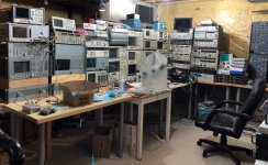
Amusing. R.N.Marsh is one of this forum members the best equipped with measuring instruments of all kind.
Maybe, or maybe not
 . You certainly missed the attached from 2018.
The rest of you rant goes as usual to /dev/nul
Attachments
Interesting, good references, thanks.I wrote a short article about the history of feedback here
That's when you get out of cold water or when you're in shape?You certainly missed the attached from 2018.
(May-be "one of the" has not the same meaning in English than in French ?) The rest of your rant goes in my personal museum.
Thank you for your spirit of innovation and your sense of sharing, Damir.Thanks for all support TT.
Last edited:
Maybe, or maybe not
The rest of you rant goes as usual to /dev/nul
A pretty good collection... a good solid second place.
🙂
-Richard
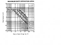
2 amps and 140 volts rated on 73 volt rails with maximum current from a 4 ohm loudspeaker would require more than 4.5 amps per output device. So it is being used above the voltage and current ratings. (The 7 amp rating is not applicable at the rail voltage.)
Attachments
Last edited:
39 watt single ended class A with 1.2A RMS current?
This thread is stuffed with super EE's 🙂D).
Now I have a request.
Please check the schematic of this newly presented amplifier:
Alpha Nirvana 39w 8ohm Class A Amp
My knowledge of electronics is mediocre, but I can calculate a few basic things.
In my opinion, to create a 39 watt @ 8 ohm pure class A amplifier, one needs 2.2 A RMS current swing, as 8 ohm x 2.2 A RMS makes 17.6 VRMS, or 39 watt.
Now in this design the pk-pk current is 2 x 1.7 = 3.4 A, which is 1.2 A RMS.
When so (but correct me if I am terribly wrong) this would mean that the amplifier will be in pure class A up to some 12 watt with an 8 ohm load, and to reach full power would switch to class B.
In other words, I'd call this design a rich biased class A/B amplifier (again...with my basic knowledge).
I already received a comment which says that the bootstrapping in the output stage is a clever trick to reach maximum power (voltage swing able to hit the power supply rails), but how about the pure class A thing? Is the needed current swing also there to keep this amp in pure class A?
What am I missing?
How about the 92 watt power dissipation of a single pair IRFP240/9240?
Last edited:
How do Scintillas sound? For being so difficult, it better have a good reason.
They are really extremely room AND amplifier dependent.
I know a place here around where a pair of them play.
The room was designed from an acoustic guy, the owner plays Steinway Model C in the same room at near professional level with high approach for natural sound, they are driven by a pair of the biggest AVM Monos made today, i had the fun to rebuild the SC at Original level, just minor mods for reliability and nice connections.
They reproduced classical music with breathtaking naturally details and effortless punch at the same time. Upper end really transparent, not bright, voices even with choirs detailed and powerfull until earbleeding levels if desired, instruments clearly and presenting their character superb, the lower end deep tight or fat, depending of source. Imagination for me is 3D, of course depending of record, maybe oversized with good focus, hard to describe, but roomfilling. Most important for me, they presented the music to me like an invitation to unterstand the musicians expressions.
If you are in switzerland once, i would be glad to arrange a meeting there to get an impression, the owner would love to do that for interested music lovers. High Enders please behind of the queue.
With other words, a musical dream, BUT :
I had also Scinnies here, very good , but sound not even as good as there.
Krell MDA 300 as power driver with many ampere drive capabilty, heat up time 3h until upper end was nice, electrical per month bill horrible and the SC- WAF was 9 below Zero or similar.
I heard SC in rooms with low ceiling and absorbing floor, absolutely crappy.
I count them in my top 3 and i am an Apogee enthusiastic Freak, so what....
I run Duettas at home and the FR are still in separated in parts waiting for the regeneration like an empty Borg.
Better try to get a an impression of them somehow, be your own judge.
regards
Frank
Anybody knows (looking mostly for data, not opinions) what would be the absolute worst case (from a design perspective) for a speaker impedance? I have among others a pair of Infinity Kappa 100 "amp killers" that drop under 2ohm (actually, 1.8ohm) somewhere in the bass, but the phase angle is almost zero there. I've seen other such pathological (but great sounding) speakers so I concluded that, as a rule of thumb, designing for half the nominal impedance is covering the worse case (either low impedance module, or a large phase angle) although for most cases it is an overkill. Designing for both low module impedance and 45 degrees of phase angle is IMO a double overkill, in particular in DIY. With the notable exception of something like the Apogee Scintillas, which dip under 1ohm - I call these "coned shorts".
Good luck in the real world.
daanve
When considering Class A operation it probably makes more sense to look at peak class A output power since the question you are trying to answer is ‘up until what output power does the amplifier remain in class A ?’
The peak output current in a class A amplifier is 2*Iq which gives a peak output voltage of 27V from which you can then calculate the power.
Last edited:
daanve
When considering Class A operation it probably makes more sense to look at peak class A output power since the question you are trying to answer is ‘up until what output power does the amplifier remain in class A ?’
OK....then what is peak class A output power of this amplifier?
I run Duettas at home and the FR are still in separated in parts waiting for the regeneration like an empty Borg.
regards
Frank
Hi Frank,
Hopefully early next year I will get to experience a recently rebuilt pair of Duetta signatures. The owner is angsting over amplifiers for them at the moment 🙂
- Status
- Not open for further replies.
- Home
- Member Areas
- The Lounge
- John Curl's Blowtorch preamplifier part III