If helping misfits such as myself count, Dan helped me for over a hour on the phone from Aus to US on his dime!
No biggie, I get three hours/month to burn on my $40.00/month phone plan, it was fun to spend part of it helping out, why not.
I got more plans for simple/reversible things you can do for your Parasound, send me an sms when you have time to talk if you like.
I got more plans for simple/reversible things you can do for your Parasound, send me an sms when you have time to talk if you like.
Last edited:
Agreed. 100 ohms.
Best part, they are magnetically orthogonal.
And, using six cables massively paralleled, four ohms.
At 10 microsecond speeds. Measured, documented, published.
Jn
Best part, they are magnetically orthogonal.
And, using six cables massively paralleled, four ohms.
At 10 microsecond speeds. Measured, documented, published.
Jn
Thanks, yes I know that is rated impedance, I am interested to confirm 100R/4 when wired in parallel, and a sweep look at transition band and finding of frequency where rated Z (TL behaviour) kicks in.....how does four parallel pairs (different twists) in one sheath actually behave ?.
What is the effect of either way slight mismatch as I likely have, is it worth dialing in with a variable resistance/SOT of some sort ?.
Just yesterday I fitted 26R (2x13R MF 0.6W) at LCR speaker terminals Cat5 connected to an AV receiver with SMPS and Class D amps.
This system pretty much only gets used for TV/games as it was I couldn't stand it, suddenly it sounds better on TV and suddenly it sounds great on music, really great, in some ways better than my analog AB amp receiver.
Speaker cable RF termination is an 'elephant in the room' as to why Class D amps can sound all wrong ?.
Last edited:
100/4 is correct for characeristic Z. However, the characteristic Z doesnt become constant until around >100KHz. At AF, the Z is much higher.
So term cable at 26 bring all freq (AF and HF) closer to same Z.
The characteristic impedance is a function of the line only. The input impedance of a line is a function not only of its characteristic impedance, but also of its loading impedance and electrical length (or physical length and frequency). They are equal when the line is loaded in its characteristic impedance
-RNM
Last edited:
At 10 microsecond speeds. Measured, documented, published.
Link?
I enjoy the Pass Labs reaction: meh, use 1 pair of vertical MOSFETs per 30W rated output, just pay the money and you get the reliability. And your reputation isn't soiled by field failures & angry (ex)customers.
Pretty much how many pro amplifiers are designed. Build a few, let sound companies beta test them. If there are output failures add more.
One previously respectable manufacturer had standard parts selected by the manufacturer for higher voltage use. They bought enough at the time that if you bought the base part, it just met spec.
Thank you all. So. we are back to what i said in #31055 and 31059.
Exicon Lateral MOSFETS - Our Product Range
The dual device/package.
No. For a high power amplifier, lateral MOSFETs are the worse option. That’s because their transconductance drops quickly at high drain currents. One of those double laterals has a transconductance of 2S, compared to 5S for the usual vertical MOSFET. This means you need x2.5 more lateral output devices to get the same current capability. It is true that the same transconductance collapse makes the laterals very reliable, much harder to smoke compared to the vertical counterparts.
But this won’t help much if the amp bursts into oscillations, which I believe is what’s happening to yours, as the root cause for the crash and burns. You and Dadod are learning the hard way, on your time and dime, a classic lesson: there is no free lunch when it comes to negative feedback. Which is: for any fixed frequency compensation order (2, in your case) increasing the loop gain (that is, ultra low distortions) always comes with a stability penalty, there is no way around. Reason is, audio amplifiers are minimum phase systems, gain and phase are not independent and the maximum feedback theorem applies. Dadod was told multiple times, by myself and others, that pushing his amp ULGF to 3-4-5 or even 6MHz is not without a stability price which may not be easy to identify by simulation, due to the complex multi loop feedback structure, but nevertheless the limitations are unavoidable there. When I see a very high ULGF, with a second order frequency compensation network, I don’t need any fancy simulations to know that the stability is, somewhere, compromised... Dadod choose to ignore the warnings and here we go... this is feedback theory, one of those pesky unforgiven EE things.
Last edited:
Thanks, 100kHz is the answer I was looking for.100/4 is correct for characeristic Z. However, the characteristic Z doesnt become constant until around >100KHz. At AF, the Z is much higher.
So term cable at 26 bring all freq (AF and HF) closer to same Z.
Sure I studied RF and long line theory back in the day.The characteristic impedance is a function of the line only. The input impedance of a line is a function not only of its characteristic impedance, but also of its loading impedance and electrical length (or physical length and frequency). They are equal when the line is loaded in its characteristic impedance
My question is can somebody (you maybe ?) do some measurements to get actual numbers, versus theoretical ones please ?.
If critical termination cannot be achieved/confirmed, is it better to guesstimate higher or lower loading resistance than calculated cable impedance value and what are the ramifications of return energy polarity according to such under dumped or over damped mismatch ?.
I do not see the transconductance dropping off with an increase in current for the ECW20N20 device, I see it rising, refer to the attached graftNo. For a high power amplifier, lateral MOSFETs are the worse option. That’s because their transconductance drops quickly at high drain currents. One of those double laterals has a transconductance of 2S
Attachments
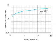
I do not see the transconductance dropping off with an increase in current for the ECW20N20 device, I see it rising, refer to the attached graft
The graph shows the transconductance up to Id=14A only, well under IDmax=16A. That’s the region where transconductance starts to drop quickly, so that lateral mosfets are self protecting. That, and the Vgs positive tempco at high currents helps as well. Meaning that laterals self limit their drain currents, unlike verticals and bipolars.
Last edited:
I am afraid I do not have one, sorry.Link?
I fabricated a 4 ohm low inductance resistor used at 4.5 Kelvin, made a stripline that transited from room temp to 4.5K, and ran a 15 foot cable made of 6 cat 5e cables set in parallel to drive the resistor at 10 amps square wave. 10 uSec rise, varied width.
The physicist wrote a paper, some conference, some paper...I do not know where..
If you have any questions, please ask. I will answer.
Jn
No. For a high power amplifier, lateral MOSFETs are the worse option. That’s because their transconductance drops quickly at high drain currents. One of those double laterals has a transconductance of 2S, compared to 5S for the usual vertical MOSFET. This means you need x2.5 more lateral output devices to get the same current capability. It is true that the same transconductance collapse makes the laterals very reliable, much harder to smoke compared to the vertical counterparts.
But this won’t help much if the amp bursts into oscillations, which I believe is what’s happening to yours, as the root cause for the crash and burns. You and Dadod are learning the hard way, on your time and dime, a classic lesson: there is no free lunch when it comes to negative feedback. Which is: for any fixed frequency compensation order (2, in your case) increasing the loop gain (that is, ultra low distortions) always comes with a stability penalty, there is no way around. Reason is, audio amplifiers are minimum phase systems, gain and phase are not independent and the maximum feedback theorem applies. Dadod was told multiple times, by myself and others, that pushing his amp ULGF to 3-4-5 or even 6MHz is not without a stability price which may not be easy to identify by simulation, due to the complex multi loop feedback structure, but nevertheless the limitations are unavoidable there. When I see a very high ULGF, with a second order frequency compensation network, I don’t need any fancy simulations to know that the stability is, somewhere, compromised... Dadod choose to ignore the warnings and here we go... this is feedback theory, one of those pesky unforgiven EE things.
Why you are so conservative? ULGF of about 1MHz was used in amp design with quite slow output transistors, and now when there much faster ones why not go for higher ULGF? How to make progress with such fear of failure, and no, the amp does not oscillate. I used fast drivers and power MOSFETs (no triple) just for that reason to get low phase shift there.
Why you are so conservative? ULGF of about 1MHz was used in amp design with quite slow output transistors, and now when there much faster ones why not go for higher ULGF? How to make progress with such fear of failure, and no, the amp does not oscillate. I used fast drivers and power MOSFETs (no triple) just for that reason to get low phase shift there.
This shows clearly that you did not understand the matter, I’m sorry. To paraphrase, you can’t make progress by assuming speeds greater than the speed of light. Unless you are Zefram Cochrane, of course
Last edited:
How do Scintillas sound? For being so difficult, it better have a good reason.Apogee Acoustics Scintilla: Impedance a measurement of the true horror of the scintillas. You want to own them just to have an excuse to build a monster amp that can handle them (or is that just me?)
This shows clearly that you did not understand the matter, I’m sorry. To paraphrase, you can’t make progress by assuming speeds greater than the speed of light. Unless you are Zefram Cochrane, of course
That is exactly an answer I expected from you.😀 Thank you for your so detail explanation.
Last edited:
Amusing. R.N.Marsh is one of this forum members the best equipped with measuring instruments of all kind.But this won’t help much if the amp bursts into oscillations, which I believe is what’s happening to yours, as the root cause for the crash and burns. You and Dadod are learning the hard way, on your time and dime, a classic lesson: there is no free lunch when it comes to negative feedback.
Do-you imagine he undertook this collection for their great aesthetic beauty, as we collect artworks ?
Rather than the question of an instability of this amplifier, which, obviously, Dadod and R.N.Marsh have considered before you, the question I ask myself is to understand what events in your life have made you so scornful and so aggressive in most of your interventions.
May I also give you a "free lesson", as you say and with all due respect: There is a choice to make, as regards to reliability, between performance and margin of safety. The design of a truck and a formula one are not to be considered in the same way.
You should be able to understand that some of us find it more fun to be a mechanic in the racing pits than a chain worker in the dapper city of Motown. At the price, sometimes, of a few extra hours.
If I have, at times, paid my seat to see a formula one race to the limit of the mechanics and talent of the drivers, I never paid my place on a highway to see the trucks passing by.
Last edited:
To tell the difference between mono and stereo? 😉If helping misfits such as myself count, Dan helped me for over a hour on the phone from Aus to US on his dime!
How do Scintillas sound? For being so difficult, it better have a good reason.
I've never had the pleasure and I know all apogees are marmite speakers that are loved or hated. I suspec that half the pride of ownership is the fact that you have the monsterblocks required to actually get sound out of them.
Both JC and NP do amplifiers that will grab them by the scruff of the neck. Of course Nelson also makes amplifiers that will drive almost nothing as well which gives him the award for most coverage of the options 🙂
- Status
- Not open for further replies.
- Home
- Member Areas
- The Lounge
- John Curl's Blowtorch preamplifier part III