
I just don't get it. Yes folks we all need to get "up to speed" on alien technologies and every EE school needs to add a graduate course in design that uses the back issues of Audio Amateur as its text.
Last edited:
I just don't get it. Yes folks we all need to get "up to speed" on alien technologies and every EE school needs to add a graduate course in design that uses the back issues of Audio Amateur as its text.
I get it perfectly. Lacking EE101 seems to be a prerequisite for successfully claiming an audio secret sauce that would instantly create a better sound. An "High End Audio" program or major should specifically forbid taking any EE courses as a prerequisite. Maxwell, Ohm, Feedback Theory, Shannon and Signal Processing are in particular dangerous. Quantum mechanics is allowed, keywords only.
Last edited:
Thinking deeper to this, I think it needs to be explored.I attribute this to the fact that distortion does not change with Z load, freq or power level.
And the best way, in my book, is to separate those 3 factors, to figure out one by one, the influence of each one of them, both in measurements and listening (because, as far as most of us have experienced, measurements without listening has no meaning and and vice versa).
The question, here, is to figure out why (or if) improvements in measurements result don't always increase our listening pleasures.
My previous tip (RLC+RC networks applied to speakers) explore the first one (Z load linearity).
The second one (freq)) is the reason why i tried this design:
Pizzicato, a 200W low distortion CFA amplifier
It is a CFA with a very high OLG (as a VFA) and a compensation network that works in frequency like most of the VFAs: Feedback ratio that begin to decrease at relatively low freq (~1kHz) that could be compared with an other more traditional CFA version (less feedback ratio at low frequencies, but flat up to 10KHz). IE: More local feedback, less global one. Same amps with just a different compensation.
The third one (Power level Distortion changes) seems impossible to me. Unless we add a unwanted distortion generator high enough to hide the distortion variation with power of any amp, there is no way I know to design an amp with very low distortion that will not change its distortion level with the signal level. But when the distortion level is so low that nobody could bring believable arguments to prove their audibility, what's the hell ?
Exploring the thresholds of distortions audibility was the reason why I added an optional error correction circuit to my amp project.
I'm very impatient to can listen to it and learn a little more about all those aspects.
Last edited:
Hi T, and Zung. It is always good to see your contributions. T, the design you chose is a pretty darn good one. The only question (minor) that I have is the exclusion of gate resistors on the output devices. Is it totally stable without them?
Joe's tube circuit is also interesting. This sort of thing has been done before, and it works!
Joe's tube circuit is also interesting. This sort of thing has been done before, and it works!
Last edited:
The third one (Power level Distortion changes) seems impossible to me. Unless we add a unwanted distortion generator high enough to hide the distortion variation with power of any amp, there is no way I know to design an amp with very low distortion that will not change its distortion level with the signal level. But when the distortion level is so low that nobody could bring believable arguments to prove their audibility, what's the hell ?
Exploring the thresholds of distortions audibility was the reason why I added an optional error correction circuit to my amp project.
I'm very impatient to can listen to it and learn a little more about all those aspects.
Richard measured this amp, he knows what he talks about.
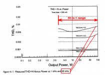
Attached THD20k at different input levels - means output power.
Attachments

Last edited:
... The only question (minor) that I have is the exclusion of gate resistors on the output devices. Is it totally stable without them?
...
?
According to the latest revision I can find:
The gates are well cared for, R41/3/5/7, 470 ohms for the N leg, and R42/4/6/8, 300 ohms for the P leg.
If only we could get rid of the input cap (C1, 100uF).
What did you do for the other 1094 days?Hi Richard, I have been working on this for three years:
That's very good. Over a 30-to-1 range of inputs (from 0.1V to 3.0V), THD-20 stays pretty close to 0.0015%.Attached THD20k at different input levels - means output power.
For comparison, here's the unsophisticated "teaching amplifier" BC1, from Bob Cordell's book. Chapter 4 in the 2nd edition. They're working to make PCBs available to diyAudio members sometime soon, so I have been told.
Over a 30-to-1 range of outputs (hence inputs too), THD-20 for 8 ohm loads stays pretty close to 0.003%. But, unlike the plot you showed, it never exceeds 0.005% across that 30-to-1 range.
Congratulations to both amplifiers and to both amplifier designers!
_
Attachments
I just don't get it...
Hi Scott, just letting you know that the "0.1dB" challenge has not been forgotten and the question of corresponding measured distortion on the acoustic side, has not been forgotten. I have acquired the measurement microphone I wanted to use, that is about as good as I am able to get. Flat over four decades, fast impulse response and little post ringing, a recognised measurement microphone that Stuart Yaniger would be familiar with. Within a week or two, before Xmas for sure. Joe
Maxwell, Ohm, Feedback Theory, Shannon and Signal Processing are in particular dangerous. Quantum mechanics is allowed, keywords only.
Mr. Marsh is the Zefram Cochrane of audio or maybe uncle Ernie.
This is an ultra-simplified diagram, not even the required coupling caps are shown, the key is those four resistors. They basically control the tube
Tube guys and gals on DIYaudio call this a "shunt Schade". Current thought is leaning towards a high impedance drive, like pentodes, making what was once called a transconductance/transadmittance amplifier. Input resistors are then composed largely of the drivers' anode load resistors.
All good fortune,
Chris
Since we took a side trip to the moon a little bit back, I thought I'd mention the real trip to the moon, Apollo 11.
There is an interesting documentary on the moon shot consisting entirely of actual footage, no talking heads, actual audio, excellent editing, and gorgeous film quality. Most of the footage hadn't been widely seen as it is the actual film shot, not videotape or telecine from the time.
I loved the audio tracking shot where they switched locations around the launch area and followed with the local audio intact from the launch control feed.
So much better than that thing the commercial studios put out last year.
Its on the usual steaming sources but I saw it from the Blu Ray disc and its well worth finding that.
Apollo 11 (2019) - Rotten Tomatoes
cheers
Alan
Thanks Mark for mentioning the BC-1 design. It is excellent performance imo for a rather simple and un-complicated design. I did listen to my proto, in mono since I only built one proto myself. It sounded good to me but that is not saying a whole lot.They're working to make PCBs available to diyAudio members sometime soon, so I have been told.
The graphs you showed I believe are from the first rev of proto boards I had done for Bob. I have completed the clean up pcb design the way I originally laid them out but that was done with almost no ME chassis design in mind. The issue is packaging for which me and Bob both admit that we are not very good at it. Bob was pushing for me to re-configure the output stage to fit into a DIYAudio chassis, so that means doing a 3rd board, just for the protection ckts and size down the OPS to fit the existing HS hole patterns on the DIYAudio universal HS drill guide. I will work on that once we get the DH-220C design completed.
I like the way I configured the BC-1(OPS) with the protection circuits, all contained on one board, since I do not like excessive wires and connectors. But the physical world will dictate otherwise.
So it is in the works, it is just a slow go. Open to ME suggestions. I posted a pic of the initial BC-1 proto in the book thread. Cheers Rick
Last edited:
That's very good. Over a 30-to-1 range of inputs (from 0.1V to 3.0V), THD-20 stays pretty close to 0.0015%.
For comparison, here's the unsophisticated "teaching amplifier" BC1, from Bob Cordell's book. Chapter 4 in the 2nd edition. They're working to make PCBs available to diyAudio members sometime soon, so I have been told.
Over a 30-to-1 range of outputs (hence inputs too), THD-20 for 8 ohm loads stays pretty close to 0.003%. But, unlike the plot you showed, it never exceeds 0.005% across that 30-to-1 range.
Congratulations to both amplifiers and to both amplifier designers!
_
8 Ohm loads are pretty easy.... the THD is very low down to 2 Ohms with DaDOD's amp.
.001% with 8 and .002% with 4 Ohm load. Lower power and freq., distortion is well under .001%
What short memories some have. I explained why the >>20Khz distortion was important to be low as well. ... because of the HF present in many DAC outputs.
THD above 20Khz is where the CFA excells over VFA.
THx-RNMarsh
----------------------------------------------------------------------------
PA does considerably more than 200W/chnl with 4 Ohms

.0035%/1Khz at 400W/4
Wanna see something even more interesting??
+/- 40vdc on a 5534 running just fine.
 7/24/2016
Last edited:
Mr. Marsh is the Zefram Cochrane of audio or maybe uncle Ernie.
I do not really exist.
I tried taking a selfie in the mirror but there was no picture.
-RM
Last edited:
Wanna see something even more interesting??
+/- 40vdc on a 5534 running just fine.
View attachment 799084 7/24/2016
I guess Strawbs album Hero and Heroine was playing through.
Tube guys and gals on DIYaudio call this a "shunt Schade". Current thought is leaning towards a high impedance drive, like pentodes, making what was once called a transconductance/transadmittance amplifier. Input resistors are then composed largely of the drivers' anode load resistors.
All good fortune,
Chris
Thanks, yes, good analysis re input resistor/driver load. In this instance that first input resistor is 150K and also a tiny parallel cap (a few pF) in parallel and a 20KHz flat o/p transformer becomes 100KHz flat. Without it, somewhere in-between. I did not show that the Grid voltage is just over 1V RMS and since the Anode is 15V, the 'open gain' of the tube is 14x, but the overall 'closed gain' is 1.5x. I have to say, it sounds like nothing I have heard before.
BTW, the output impedance on the secondary is about 2.3 Ohm.
Last edited:
Dadod, yes I know your amp that is the most impressive CFA I've seen.Richard measured this amp, he knows what he talks about.
Attached THD20k at different input levels - means output power.
(Could-you provide the same curve at 1kHz ?)
i was not questioning-it, but the audibility of all those factors Richard was talking about.
BTW, why did not you choose laterals? For economic reasons ?
I was sure such a gentleman can't really exist in our actual world ;-)I do not really exist.
I tried taking a selfie in the mirror but there was no picture.
I have a question about harmonic distortion levels at 20KHz. How could-we hear such frequencies ? May-be it is only the IM tat is more or less correlated ?
Last edited:
yeah I'd think I'd be a bit more concerned about this issue than your >>20Khz distortion was important to be low as well. ... because of the HF present in many DAC outputs.Now that I am here, I intend to replace all the output devices with more rugged ones but the pin out is different. It has not been reliable enough to go anywhere with it. I will find out why/how the outputs keep blowing up. BUT...
maybe it is better to stick with LP's & tape 🙂
Last edited:
When I find blown output transistors the issue of the failure mode pops up. Did one output fail or a bunch. Did any fail open or did they fail shorted?
A single output shorted tends to indicate exceeding the Safe Operating Area. The common cause is non-uniform heatsink temperatures.
An open transistor indicates a significant amount of current past the rated maximum.
Lots of shorted outputs hints at failure to share the load between output transistors. (Sequential failures that happen quickly.)
These issues often pop up when the bias system does not track the thermal changes in the output bias stages. For those I check the voltage drop across the output stage vs temperature. Using a totally bipolar output stage tends to track nicely the usual bias voltage drop circuit if properly thermally coupled. I don't know the thermal response of a mixed bipolar/FET output stage. (I suspect it is strongly dependent of the type of FET.)
Of course one important test is to be sure the output stage is not oscillating. That involves looking at frequencies at least to 500 megahertz.
I have been looking at building one of these amplifiers. My first pass look doesn't like the arrangement of the power rail filter capacitors local to the output devices. These are capable of handling the large surge currents at audio frequencies but with the internal inductance combined with the layout inductance may not damp high frequency oscillations. But then I don't know if that is a real issue.
I do know simulating high bandwidth circuits without including stray inductances has burned me in the past.
Last edited:
- Status
- Not open for further replies.
- Home
- Member Areas
- The Lounge
- John Curl's Blowtorch preamplifier part III