Sometimes the problem has been with over reliance on old hearing research
that is impossible to replicate or critique because the exact details of how it
was performed are unknown
Some of that research was done on men with military-related hearing damage.
Yes, they were around $900 KEF direct as a refurbished pair.
These do need about a month of playing to break in.
Using Sound Organisation lead filled stands with custom wood tops
and a cork interface to the speaker bottoms.
Niice!
Thanks.
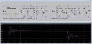
Attached is the filter I think I'll use; it's based on a 4th order kit from eBay. Original on the left and green curve, modified with dampers on the right and purple curve; C4 is 2x6.8n because that's what I have in my junkbox. Your comments are very welcome.
To start to understand what is apening you can simulate the source as a sine wave with 100 milliOhms source impedance AND the load as a rectifier bridge with a short conduction angle and appropriate current. Then introduce short transients (100uS) with maybe a 1 Ohm source and 200V peak. You do need to model the inductors since they may well be saturating.
Still build and test is the best way to verify performance and that properly requires some expensive specialzed stuff.
ABORT! Those are CMCs, not inductors. You do not know the actual series inductance, but it is likely 1/100th to 1/300th the common mode inductance. You need to add a K statement to the simulation to show they are coupled inductors.
Well done!
Here's a re-run with various coupling factor K's. At K=1, the inductances cancel out (purple curve), any other values from .95 to .99 ring like hell with the same damping as before. I'll look more into this and report later
Attachments
As for your claim about collateral damages, any list?Cool, man,cool.
Comediante! Tragediante!
Funny claims are ...funny.
It may well ring at LF - which is what is happening because the ringing is at low single digit kHz. Your rectifier and filter caps will take care of that, but not HF (100's of kHz to MHz) on the mains because that just blasts through onto everything. Example: power line communications.
I would expect that the filter peaks first, but then attenuation after the turnover frequency is very steep, so LF ringing is actually part of the deal. Have you done a frequency sweep?
I would expect that the filter peaks first, but then attenuation after the turnover frequency is very steep, so LF ringing is actually part of the deal. Have you done a frequency sweep?
Hi Zung! We tried these sorts of commercial filters on audio products and now we tend to avoid them. Trust your ears.
Hi Zung! We tried these sorts of commercial filters on audio products and now we tend to avoid them. Trust your ears.
Right on!
Then again, I think we all agree AC is evil with all the digital fecies in it. I'm just curious to (briefly) explore whether the commercial filters are even remotely suitable for audio. They are basically low pass filters, but the 3 I've dissected peak and therefore ring like hell.
I still think we can do it right with a Bessel/Butterworth kind of filter, and the right components. Any volunteers for the math? Gentle folks, at least the 1st part is no black magic. 🙂
... Have you done a frequency sweep?
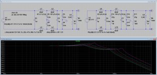
Here you go, but bear in mind the damping network is NOT optimized.
Attachments
Filters that couple line and neutral to ground (and the chassis) are particularly troublesome. If ground is not ground but some impedance above ground all the noise on both will be added to whatever is on the ground leg to start with. If the ground pin is disconnected then the chassis is at 1/2 the line potential, at least until you touch it.
Medical grade filters are better since leakage to ground is strictly limited. Still not great if you don't need one. A well designed power transformer can be a really effective line filter.
Medical grade filters are better since leakage to ground is strictly limited. Still not great if you don't need one. A well designed power transformer can be a really effective line filter.
Here you go, but bear in mind the damping network is NOT optimized.
FWIW the filter is peaking at typical switching supply frequencies. I don't think that is what you want.
... all the noise on both will be added to whatever is on the ground leg to start with...
Makes sense: common mode noise plus differential mode noise plus ground noise plus all interactions of the above.
... If the ground pin is disconnected then the chassis is at 1/2 the line potential, at least until you touch it...
That's close to the infamous "death cap" commonly found in US guitar amps, even though I've never seen any verifiable report of demise. But having actually experienced this in person, I can assure you it's unpleasant. 🙂
... A well designed power transformer can be a really effective line filter.
Sadly out of reach for a lot of humble DIY amateurs like myself. I did buy an isolation transformer for my nephew's Hifi, but I haven't done any sort of listening yet.
FWIW the filter is peaking at typical switching supply frequencies. I don't think that is what you want.
The peakings can be smoothed out by adjusting the damping network; I've yet to do it, that's why I capitalized "NOT".
Zung, trust 1audio (Demian) or Richard Marsh. They have plenty of professional experience with filters like these and even more extensive versions.
Zung, Rcore transformers from China are a good bet for better isolation with individual products. We are designing a dual transformer arrangement with my new JC-1+ power amp. We are using an R-core for the higher voltage driver supply, and a 2200W toroid for each channel. Best of both worlds, I hope.
I wholeheartedly agree. Even when there's no noise present, they capacitively couple the power line frequency current into the ground, which is never Truly Ground, so it can CAUSE a voltage difference and hum between a device that has the circuit ground connected to the chassis and some other device that's at a different "ground" potential.Filters that couple line and neutral to ground (and the chassis) are particularly troublesome.
And unless your ground wire is a superconductor, it's ALWAYS "some impedance above ground." The lower the better, but it's never zero.If ground is not ground but some impedance above ground
IMO it's best to keep any (non-fault) current from going through ground, and that means having no current going between it and either side of the power line.
... We are using an R-core for the higher voltage driver supply, and a 2200W toroid for each channel. Best of both worlds, I hope.
That's smart: R-core for isolation of the sensitive part where the current demand is low and constant, toroid for the power part for minimizing the widely varying stray magnetic field. Anything else I missed?
The Chinese irons are getting better and better these days. Last year, my (tube🙂) preamp fried its HV stabilizer, so I tried a LCLC filter instead. For the head L, I used a choke sourced from Germany, and it buzzed like hell, I mean mechanical vibrations. I then swapped in a Chinese choke with similar spec's, and it's quiet as a grave, even with a make-shift stethoscope (a screwdriver!).
Hi Zung! We tried these sorts of commercial filters on audio products and now we tend to avoid them. Trust your ears.
It's interesting you should say this.
Years ago we were prototyping small (300VA or so) bal power transformer with schaffner type filters on OP. A good friend who has been in hi end for a very
long time said 'those filters always muck my sound up, I never use them'. I laughed.
He felt they always, to some degree, sucked out the richness of the music resulting in often more detail but usually a less natural sound.
After making a lot of protos and trying many different filter arrangements, I have to say he was, for the most part, right.
Recently for kicks, I made another balanced supply with very aggressive filtering. This time I also used snubbing (R/C) networks on the OP to try and attenuate any transformer ringing from leakage inductance reacting with caps.
Even on my guitar amp (AC30) it had same effect that I remember. Super clean, almost leached out midrange, which at first bowled me over with pristine clarity.
After many on / off trials, I decided it actually sounded worse, becoming less
natural sounding.
T
+1 and with Demian too.Zung, Rcore transformers from China are a good bet for better isolation with individual products. We are designing a dual transformer arrangement with my new JC-1+ power amp. We are using an R-core for the higher voltage driver supply, and a 2200W toroid for each channel. Best of both worlds, I hope.
As transformers all along with diodes bridges will produce anyway parasitic signals up to high frequencies, even with a clean AC, better concentrating on DC filtration that will reduce both in once. And PSS of the electronic for what remain, of course.
And, as said Demian and JC , may-be more important, avoid as much ground leakages you can (Rcore for low power devices, shielded toroid for high power ones ).
*On my opinion*, AC filtration is more useful in specific situations (When you are near a radio or TV emitter, as an example) and it need to design the filter for this particular target.
Right on!
I'm just curious to (briefly) explore whether the commercial filters are even remotely suitable for audio.
No. They are not suitable.
THx-RNMarsh
FWIW the filter is peaking at typical switching supply frequencies. I don't think that is what you want.
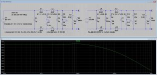
For the sake of completeness, here's a run with somewhat optimized snubbers. All that's left is a small peaking at about 2dB/10KHz
In light all the valuable inputs here, I'm reconsidering fitting an AC filter at all. Especially because of the chokes, with this most burning (for me) question: are ferrite core inductors evil?
Thanks to all for your answers.
Attachments
- Status
- Not open for further replies.
- Home
- Member Areas
- The Lounge
- John Curl's Blowtorch preamplifier part III