I have always known we share a common view. Perhaps a few minor details need hashing and clarification, but that is all..😉
jn
That is perfect.
We have to take care in the measurements to avoid excessive BL(x) as it quickly dominates everything, also there is a chance of canceling effects. With no Klippel data on a driver all we can do is try restrict excursion..
Your right. I forgot mechanical limits.
Jn
I need you to be clearer on "diff signal" so I measure the right place. I already went off in the wrong direction once. I can get waveforms and may be able to get an X/Y display (not sure yet).
With the top terminals of the coils connected together and to the amplifier output, the difference is the voltage between the other ends of the coils.
Since the drive coil is connected to ground, the pickup coil end shows the distributed resistance of the drive coil, ignoring all reactive voltage caused by the intimate coupling of the two coils.
I can see using this difference as a diagnostic tool. Useful for examination of the coil resistance including eddy loss equivalent resistance and acoustic transfer equivalent resistance, both during voltage drive as well as during current drive.
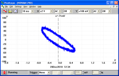
I did not mean x/y. I meant two waveforms on a two channel scope.. Top trace being drive signal, that being either voltage out of the amplifier, or current through the current drive system, and the second being the difference signal.
An x/y would be capable of displaying non linearity quite clearly, especially with current on one axis and difference on the other, that's not a bad idea, I like it.
jn
You could drive the speaker with another speaker and measure the difference between voicecoils. This way we know how well the voicecoils are matched and can better judge the results from subtraction.
Also the second voicecoil output could be scaled in the measurement to null out mismatch. Put a trimmer across it and take feedback from the wiper, measure at the end of the coil. Or if the mismatch is negative, take the measurement at the wiper. One of these should provide a better null.
Also the second voicecoil output could be scaled in the measurement to null out mismatch. Put a trimmer across it and take feedback from the wiper, measure at the end of the coil. Or if the mismatch is negative, take the measurement at the wiper. One of these should provide a better null.
Last edited:
I do get some harmonic attenuation. Below is without vc feedback and then with voice coil FB.
Not a lot ... About 50% reduction. Should be audible, though.
with no VC feedback.

with coil in FB.

THx-RNMarsh
Not a lot ... About 50% reduction. Should be audible, though.
with no VC feedback.
with coil in FB.
THx-RNMarsh
Last edited:
You may be able to improve the distortion using the trimmer I mentioned with feedback from the wiper. If not, swap the voicecoils and try again.
You may be able to improve the distortion using the trimmer I mentioned with feedback from the wiper. If not, swap the voicecoils and try again.
OK. and show me a diagram of your wiper to amp connection. trimmer value?
THx-RNMarsh
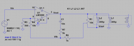
R1 is the trimmer. It works if the feedback coil is slightly larger than the other coil, so you may have to swap coils.
I think 10k is a good value since it is at least 1000x Re. The impedance of the trimmer shouldn't affect the feedback too much unless the coils are grossly mismatched.
EDITed for trimmer value. 100k might actually be better, the better the coils are matched the higher value trimmer you can use.
I think 10k is a good value since it is at least 1000x Re. The impedance of the trimmer shouldn't affect the feedback too much unless the coils are grossly mismatched.
EDITed for trimmer value. 100k might actually be better, the better the coils are matched the higher value trimmer you can use.
Attachments
Last edited:
Not much difference when coils are exchanged. First coils used give a little more 2H atten.

THx-RNMarsh
THx-RNMarsh
Last edited:
I wonder if you can get a better result with strict current drive? Or will current drive have worse results?
Is the voicecoil bifilar or co-wound? Does it have an aluminum former or a shorting ring?
I wonder what is creating the 125Hz tone?
Is the voicecoil bifilar or co-wound? Does it have an aluminum former or a shorting ring?
I wonder what is creating the 125Hz tone?
Is the voicecoil bifilar or co-wound? Does it have an aluminum former or a shorting ring?
From literature it is wound one on top of the other. Dont know anythig else about it without ripping it apart.
It is a PYLE(R) Power model PLPW6D
-RNM
Last edited:
Blimey, those are under £10 at the moment in UK. The larger ones aren't much more. I wonder if anything useable could be made from them other than an in car thumpa thumpa.
Blimey, those are under £10 at the moment in UK. The larger ones aren't much more. I wonder if anything useable could be made from them other than an in car thumpa thumpa.
I had an idea to turn a speaker into a sensitive scale using an opto switch to keep the cone in the same position and measure the speaker current required to do so.
Now that I think about it, the same system could be used to measure the Bl(i) of a speaker. Keep adding pennies and measuring the current? You could even move the optoswitch around to measure Bl(i) at different spots.
If I am allowed to put my 12 cents, I would do this (as attached):
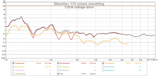
- measure THD (H2, H3) vs. frequency under standard voltage drive,
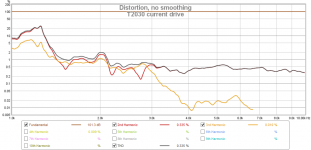
- measure THD (H2, H3) vs. frequency under current drive or with DVT correction, whatever you have available.
In my case, Beyma T2030 tweeter (resonance about 900Hz), we can see that H2 under voltage x current drive is almost unaffected. But, above 4kHz, there is a really dramatic decrease in H3 distortion for the current drive. This was shown in my previous twin-tone IMD measurements. So, if you make a H2/H3 vs. frequency, you may find where the distortion correction works and then make a FFT there.
- measure THD (H2, H3) vs. frequency under standard voltage drive,
- measure THD (H2, H3) vs. frequency under current drive or with DVT correction, whatever you have available.
In my case, Beyma T2030 tweeter (resonance about 900Hz), we can see that H2 under voltage x current drive is almost unaffected. But, above 4kHz, there is a really dramatic decrease in H3 distortion for the current drive. This was shown in my previous twin-tone IMD measurements. So, if you make a H2/H3 vs. frequency, you may find where the distortion correction works and then make a FFT there.
Attachments
I heard from many sources today is the shortest day of the year.
So I got out my tape measure and tried it on most things around here and there was no difference whatsoever. I also tried my optical range finder we use for measuring stadiums and the like and again no changes.
Then I though perhaps they meant time-wise, but the shortest day of the year is the 23 hour day in the spring when daylight savings time begins.
So I guess this is just another example of subjectivism vs. objectivism.
Daylight vs. day, semantics. A bit OT, right?
Parody! On a recurring topic.
Right now the topic is on something measurable, but is it perceptible? (Probably!)
Last edited:
Blimey, those are under £10 at the moment in UK. The larger ones aren't much more. I wonder if anything usable could be made from them other than an in car thumpa thumpa.
Yeah... quit a surprise to me also.
-RNM
- Status
- Not open for further replies.
- Home
- Member Areas
- The Lounge
- John Curl's Blowtorch preamplifier part III