Doesn't the circuit on the right look familiar? What am I missing?
Wow. Is it really necessary to explain the difference John?? It is quite obvious to even the most casual of observers.. (I love that saying)
Sigh...should I just give you hints and drag it out like ed, or should I just explain...
The circuit on the right does not separate out the voltage across the real portion of the load. It is trying to control the reactive portion. Pity they don't show a phase curve..
I separate out the real part of the speaker impedance, and control the voltage across that even though it is a distributed element.
So my scheme is so much more like current control, just not with a CVR.
I expected you to understand that..
jn
Get rid of all the gyrator stuff
Sorry, the gyrator is the base for electro-mechanical transformation in the driver. It is impossible to "get rid off" it. Your simple model (JN) does not describe the speaker behavior.
We already did that a few pages ago didn't we? This has been pretty well established.
I know. PMA is determined to use his model.
I agree. I'm trying to explain to PMA. I'm not sure if it's a case of having only a hammer so calling everything a nail, or if he's just waaay over my head...jury's still out...😀Designing the circuit isn't the problem either, it's ready for prototype as far as I'm concerned. So how much later are you talking about? What have we not done that we need to do before that?
The harmonics injected in the 3rd coil will present equally in both voicecoils. They will cancel at the feedback point. The residual will depend on the amount of feedback, unless we deliberately mismatch the coils. But then the residual will just be the nonlinearity scaled down, this doesn't give us anything we don't already know.
jn
Keantoken, please keep up the good work. Ehm, would you like to share the .asc also?
I have spent hours and hours on this. Not sure I want to just drop it casually. But that one has some errors anyway, currently I'm working on the reluctance force implementation. It probably has several full transformations to go before it's reasonably mature anyway.
That Klippel paper again makes clear that the BL(x) nonlinearity is still the major distortion contributor for large signals / high excursion and none of the simpler methods (current drive, including JN's -- degenerated or not; using the VC as velocity sensor; etc) can address it, only the driver design can (either genererously underhung VC or generously overhung with very symmetric magnetics)... or a true independent sensor MFB (still with some means to soft-limit the excursion...
I'm not laboring under the assumption I can fix any of it with current drive. My idea is to improve the model to the point where it gets similar results to the Klippel measurements and then experiment with drive methods, try to match it to real speakers, etc. Of course everyone will come up with some silly reason I can't or shouldn't do it.
There are gryator-less models, like this one which I'm using a lot (only for linear analysis, of course): Electrical Model of Loudspeaker Parameters | PROJECT RYU
Uses a simple Le model that can be corrected if needed to get reasonable results at higher freqs.
Uses a simple Le model that can be corrected if needed to get reasonable results at higher freqs.
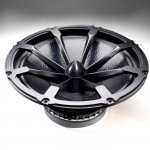
Metal formers sound premium but really are not necessary except if you are running very high power and need the aluminium to help get the heat out.
An example of speaker with an extreme design (to minimize power compression).
(Is it worth going this far?)
PMC Loudspeakers MB2S-XBD-A Three-Way Active Studio Monitor with XBD Bass Cabinet- Pair
The unique 12" Radial™ driver features two cooling systems. In addition to the conventional rear vented magnet it uses the patented, front mounted Radial™ chassis, which acts as a giant heatsink. This keeps voice coil and magnet temperatures exceptionally low resulting in superb reliability, 3dB less power compression and tight, clean bass even after prolonged periods of high SPL.
Attachments
Ok, understood, and I'm fine with that (and I've already hacked in your first, linear model from the screenshot you've posted)I have spent hours and hours on this. Not sure I want to just drop it casually. But that one has some errors anyway, currently I'm working on the reluctance force implementation. It probably has several full transformations to go before it's reasonably mature anyway.
Oops, that second paragraph in my post was meant as a general comment, has nothing to do with your work and your intents, that is.I'm not laboring under the assumption I can fix any of it with current drive. My idea is to improve the model to the point where it gets similar results to the Klippel measurements and then experiment with drive methods, try to match it to real speakers, etc. Of course everyone will come up with some silly reason I can't or shouldn't do it.
My simple model describes the exact behavior two co-wound coils will exhibit when one is driven and the other is used as a pickup coil, and they are both communicating to the same magnetic circuit.Your simple model (JN) does not describe the speaker behavior.
As configured, it cancels out ALL time rate of change of flux from the drive coil, and leaves only the IR contribution of the drive coil voltage remaining as the feedback.
It ABSOLUTELY cancels out ALL magnetic linearities and ALL magnetic non linearities, for all flux that couples to the coils.
This is the first time I have shown this concept applied to a trivially simple** device like a loudspeaker. It has been successfully applied to rather more complex devices, and the owners of that device never said "just go to the literature and stop thinking..."
While it may be your desire to kill it because of NIH, an overly complex model is not proof.
jn
**just had to put that there from my high horse...we all know the models aren't that simple..😀
Last edited:
Okay jneutron, we are on the same page. Sorry for the misunderstanding.
I wanted to do that early on, but I realized the gyrator is easier to use for various reasons.
The coupled inductor model only gives the illusion of being simpler than the gyrator. This is a case where being lazy makes you work harder.
What would be better than a gyrator would be a electrical circuit, a mechanical circuit, and a magnetic circuit in between to represent the flux loop(s).
There are gryator-less models, like this one which I'm using a lot (only for linear analysis, of course): Electrical Model of Loudspeaker Parameters | PROJECT RYU
Uses a simple Le model that can be corrected if needed to get reasonable results at higher freqs.
I wanted to do that early on, but I realized the gyrator is easier to use for various reasons.
The coupled inductor model only gives the illusion of being simpler than the gyrator. This is a case where being lazy makes you work harder.
What would be better than a gyrator would be a electrical circuit, a mechanical circuit, and a magnetic circuit in between to represent the flux loop(s).
An example of speaker with an extreme design (to minimize power compression).
(Is it worth going this far?)
PMC Loudspeakers MB2S-XBD-A Three-Way Active Studio Monitor with XBD Bass Cabinet- Pair
I'm sorry...what means this phrase "is it worth going this far?"😕
What they really need to do is drill some holes in the pole piece and the return plate, and inject helium gas directly onto the voice coil. I recall IBM doing a scheme like that on some high power CPU modules. Apparently Helium has high heat capacity for it's viscosity...
Course, you'd need oxygen sensors in the room😉
jn
Last edited:
I think I got that now and that's sure is where the beauty of your concept lies in... though I still can't exactly understand what it will do better that just plain current drive.It ABSOLUTELY cancels out ALL magnetic linearities and ALL magnetic non linearities, for all flux that couples to the coils.
PS: The Goldwood drivers will need quite some time to ship to here... but I've found another nice 6.5" DVC easier to get here in Germany, the Monacor SPH-170tc and will order it, though quite a bit more costly but hopefully also a better design to start with.
I'm sorry...what means this phrase "is it worth going this far?"😕
I meant, does the approach make a significant enough difference to justify the very high cost?
I suppose it does, if the user listens at a high SPL for a long period. But that is not a good practice in studios afaik. (The product is aimed at the studio segment.)
Not quite, it's sort of a brute-force approach. The engineering and tooling costs for that specialized basket sure have been immense, and given the small market they aim at this is reflected in the unit price.I meant, does the approach make a significant enough difference to justify the very high cost?
Precisely what schematic for this loudspeaker drive circuit are we taking about? I see a number of variations.
I meant, does the approach make a significant enough difference to justify the very high cost?
I suppose it does, if the user listens at a high SPL for a long period. But that is not a good practice in studios afaik. (The product is aimed at the studio segment.)
Hang on, people here talk about the benefit of $500 capacitors and very expensive flooby snake oil devices that, as far as anyone can tell do naff all from an electrical perspective. So surely a REAL improvement must be worth something.
To me the Volt units look a bit like the bass units a Dalek would chose, but I am sure that, in the target market they are appreciated for their performance.
To me the Volt units look a bit like the bass units a Dalek would chose
That reminds me a Davros effects box would be an interesting product.
Still dreaming of being a little kid, remember all those sound effect kits in the pages of practical electronics/wireless?
Those were the days, what have the kids got now that they can actually DO?
Perhaps get excited about some new loudspeaker concept 😀
Those were the days, what have the kids got now that they can actually DO?
Perhaps get excited about some new loudspeaker concept 😀
Last edited:
- Status
- Not open for further replies.
- Home
- Member Areas
- The Lounge
- John Curl's Blowtorch preamplifier part III