Until we have a REAL MEASUREMENT, we have virtually nothing. Demian, I hope you will find time before the 1'st of the year to make a measurement. A B&K 1" microphone should do just fine. ( I have one myself, so I know that is has low enough distortion) Let's get her done!
I disagree. We have a better understanding of the magnetics of a speaker, another diagnostic handle for development of better speakers.
I do not consider that "virtually nothing".
Jn
Well the windings have the advantage that they are covered in epoxy and insulation. What about electrolysis with NaOH?
If it can be made to work it might also be a way to convert to a former on the outside of the coil as has been mentioned a few times.
Two concerns. Any pinholes in the enamel insulation of the wire and the wire cannot support the current. Also, the former provides strength between winds.
The. Oil current will of course try to pinch the conductors together a bit, but as the coil leaves the gap in either direction, there will be wire to wire forces. The epoxy will not be very good in tension.
Oh, the wires might have been coated with a thermoset, so theremay not be a whole lot of support without the former.
Jn
Hi Scott,
Perfect then ... unless they used Aluminium wire too.
From where did you pull this knowledge? I am impressed.
-Chris
Perfect then ... unless they used Aluminium wire too.
From where did you pull this knowledge? I am impressed.
-Chris
From where did you pull this knowledge? I am impressed.
-Chris
Drano
Last edited:
Draino
Da#n you, i just spewed cognac!! It's bad enough the boat is pitching, now I gotta worry about laughter..
Classic.😛
You in yet?.
Jn
You fixed spelling. Too late, gotcha.
Actually, I like your spelling better.
Last edited:
Self supporting voice coils are nothing new and you don't need metal formers. Most use a Nomex paper. The only issue is that the coil is usually too short except in a tweeter to reach the diaphragm. I'm sure its possible to bond the coils edge to a former to extend it. Not sure there is much to gain until you are making very premium drivers. Dealing with lead-out wires and tinsel (not litz) for the flex is not a problem.
Also copper covered aluminium is a popular option for voice coils. Solders easily and is much lighter.
I forgot a cap in series with R2 above to get the DC gain back to unity. I may be able to kludge it all together if I can keep it simple. I'll probably do the amp stuff first and then test with the driver in a box.
Last edited:
Hi Demian,
The biggest problem I've seen with self supporting voice coils is that they don't take much heat before they come completely unglued. What a mess. Next to zero overload capacity.
Yamaha tweeters (they called them midrange drivers) used to fail quite easily. They were fast and efficient, but would just let go without any warning. No burning was necessary, all you had to do was to heat the glue a touch and it was all over.
I can't imagine this in a woofer or midrange, and I like having a former that will help dissipate heat.
-Chris
Epoxies have a glass transition temperature. On or near that temp, they lose all structural strength.Hi Demian,
The biggest problem I've seen with self supporting voice coils is that they don't take much heat before they come completely unglued. What a mess. Next to zero overload capacity.
Yamaha tweeters (they called them midrange drivers) used to fail quite easily. They were fast and efficient, but would just let go without any warning. No burning was necessary, all you had to do was to heat the glue a touch and it was all over.
I can't imagine this in a woofer or midrange, and I like having a former that will help dissipate heat.
-Chris
Jn
What is R2. When the gyrator pulls non linear current, how do the voice coils see that current? It looks like it can disturb the drive voltage of the drive coil , bu I do not understand your choices. Can you explain please.
Jn
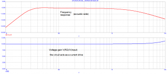
R2 is a voice coil resistance in a braked state (Re). I have not used the second coil. Instead, there is a 1:1 transformer monitoring voice coil voltage. Nonlinear and frequency dependent resistive drop on voice coil is thus eliminated in the model. Voltage across voice coil resistance equals amplifier input voltage multiplied by gain, which is 10 in this case. If the input voltage is flat with frequency, voltage across coil resistance is also flat and equal 10*Vin.
Last edited:
Hi John,
Yes, I have seen many practical examples of that where there was no evidence of heat enough to discolour the wire. I'm pretty sure if you wound the wire back on a mandrel and glued it again, then to the dome, you would have a perfectly good functioning tweeter once more. In Canada my cost to replace this driver was around $120, which would make that about $200 * to the end user. That's not completely outrageous for a very good tweeter, but not when they are so damned easy to damage.
* Standard industry markup is a 40% discount from list for parts. That's just enough to cover all the costs associated with ordering and receiving the part along with some markup. We certainly did not get rich with parts sales. Some places we only got 25% discount. At that point you're further ahead having the customer buy their own parts direct.
-Chris
Self supporting coils are also used in some high power compression drivers and seem to survive. They would not be a normal choice for a midrange or woofer since you still need the extension to reach the cone. Metal formers sound premium but really are not necessary except if you are running very high power and need the aluminium to help get the heat out. That's mostly car audio stuff. Stick to Nomex formers, they are also lighter.
The one I am familiar with is ‘Pirooma’
Pulled it right out of my a***
One of the Dr’s in the development group at the factory I was based at gave me that one 😉
Last edited:
Self supporting coils are also used in some high power compression drivers and seem to survive. They would not be a normal choice for a midrange or woofer since you still need the extension to reach the cone. Metal formers sound premium but really are not necessary except if you are running very high power and need the aluminium to help get the heat out. That's mostly car audio stuff. Stick to Nomex formers, they are also lighter.
Polyimide is a yearly high temperature material. It requires much higher temperatures to imidize, 300 C IIRC. That, polyimine coated wire, and a kapton former, good high temp capability. And it still looks like normal enameled wire.
Jn
Man, this Ipad is so creative.
Pavel becomes Patel, very becomes yearly, polyimid becomes polyimine.
It takes two or three attempts to get it to understand.
Jn
Pavel becomes Patel, very becomes yearly, polyimid becomes polyimine.
It takes two or three attempts to get it to understand.
Jn
PMA,
It looks like you are taking the non linearities through the resistance, and that IR drop is showing for the drive coil voltage.
I believe those currents should go through the drive coil. That way they couple directly to the feedback coil.
Jn
It looks like you are taking the non linearities through the resistance, and that IR drop is showing for the drive coil voltage.
I believe those currents should go through the drive coil. That way they couple directly to the feedback coil.
Jn
You in yet?.
Actually, I like your spelling better.
Final walk through in a couple of hours, closing tomorrow. I don't know how I survived playing with all the cool stuff under the sink as a kid.
I stuck a fork in a mains socket, that was exciting.......for my mum
So many stupid things growing up, just glad to be alive
So many stupid things growing up, just glad to be alive
PMA,
It looks like you are taking the non linearities through the resistance, and that IR drop is showing for the drive coil voltage.
I believe those currents should go through the drive coil. That way they couple directly to the feedback coil.
Jn
I will try to explain how it works and why my doubts about distortion reduction.
The circuit is driven from AC voltage source V1. Starting at R2 there is a speaker circuit model. Before the gyrator there is a voice coil R2 + L1. Behind the gyrator there are mechanical elements of the speaker. L4//R4 is a radiating impedance transformed to the mechanical side via 1/S^2 transformation. R8//D1//D2 were added to simulate a non-linearity, though it would be a mechanical non-linearity (like excursion dependent e.g.).
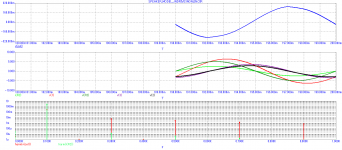
Now, the K1 trafo (1:1) is subtracting voice coil voltage as you have suggested and you are using a 2nd coil for this. Because of feedback, voltage across R2 is just V1*(1 + (R6/R5)), it does not depend on frequency or amplitude. Thus, the coil R2 + L1 (+ primary side of the gyrator) is always driven by current and this current is undistorted, it is V(R2)/R2 as far as R2 is constant. Now we have a non-linearity on the mechanical side of the driver, in the secondary of the gyrator. This non-linearity is in series with the mechanical impedances, however after transformation to electrical side it transforms as parallel! Remember that the gyrator transforms parallel to series and vice versa. Voltage goes to force, current to velocity. So, even if the primary current of the gyrator is undistorted and current driven due to feedback used, the nonlinearity in the secondary makes the velocity flow nonlinear. This is shown in the time domain plots attached.
Output signal v(out) is distorted, though the input current i(R2) is undistorted. The i(R3), representing velocity, is distorted as well, in the similar way as v(out).
So, we have clean current drive due to feedback and coil voltage subtraction, but despite of that, due to mechanical non-linearity, the velocity i(R3) is distorted (not shown) and the output sound v(out) similarly as well and there is no cure this way how to make a correction. It should have been a different circuit, different correction philosophy, IMO.
Attachments

- Status
- Not open for further replies.
- Home
- Member Areas
- The Lounge
- John Curl's Blowtorch preamplifier part III