Until we have a REAL MEASUREMENT, we have virtually nothing. Demian, I hope you will find time before the 1'st of the year to make a measurement. A B&K 1" microphone should do just fine. ( I have one myself, so I know that is has low enough distortion) Let's get her done!

Here is my schematic which AFAIK shows how it actually works.
As far as I can tell, your model is exactly what I am thinking about. PMA's model is so far over my head that I can't tell what he is exactly doing.
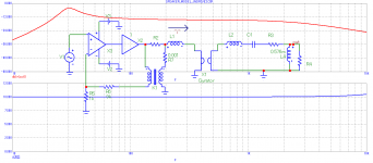
There are more ways, in principle, how to get the same result. My first attempt, several days ago, was with simple sum and subtract elements. Now attached is an equivalent, it does the same thing as Keantoken's. I needed to confirm what JN tries to achieve, then it was possible to make a model. Upper trace is an acoustical output (directivity of cone not included), lower trace is the voltage across Re, for voltage drive.
Edit: the problem is that if I put a nonlinearity to mechanical side (behind the gyrator), the circuit is not able to make a correction. It is, again, equivalent to a current drive.
Attachments
Last edited:
'Well, side with Dan, if you wish. I think that he is 'selling out'.
Strange thing to say. He singing a familiar tune fully complementary, balanced, wide open BW, low FB. What's the problem?
What eats Aluminium will probably eat the copper faster.
-Chris
NaOH? Eats the Al fast.
Strange thing to say. He singing a familiar tune fully complementary, balanced, wide open BW, low FB. What's the problem?
Scott, I think what he spoke in the video does not imply a complementary circuit.
As I understood, he said "mirror image balanced circuitry", in the context of a fully diferential (bridge tied load) circuit, isn´t it?
I don´t know his circuits...
On a second thought, he is most likely using complementary circuits as well, at least the output stage.
On a second thought, he is most likely using complementary circuits as well, at least the output stage.
I don´t know his circuits...
On a second thought, he is most likely using complementary circuits as well, at least the output stage.
I assumed he meant mirrored along both axes. This is your best bet with low feedback topologies (especially PA's).
Well the windings have the advantage that they are covered in epoxy and insulation. What about electrolysis with NaOH?
If it can be made to work it might also be a way to convert to a former on the outside of the coil as has been mentioned a few times.
If it can be made to work it might also be a way to convert to a former on the outside of the coil as has been mentioned a few times.
Well the windings have the advantage that they are covered in epoxy and insulation. What about electrolysis with NaOH?
Not sure, SY is not here anymore.
Got itI assumed he meant mirrored along both axes. This is your best bet with low feedback topologies (especially PA's).
Strange thing to say. He singing a familiar tune fully complementary, balanced, wide open BW, low FB. What's the problem?
Are you trolling JC? 😎
Are you trolling JC? 😎
Who me? I thought Dan was in the respected competitor group, I guess not. I doubt the $250,000 amps are flying out the door.
What is R2. When the gyrator pulls non linear current, how do the voice coils see that current? It looks like it can disturb the drive voltage of the drive coil , bu I do not understand your choices. Can you explain please.There are more ways, in principle, how to get the same result. My first attempt, several days ago, was with simple sum and subtract elements. Now attached is an equivalent, it does the same thing as Keantoken's. I needed to confirm what JN tries to achieve, then it was possible to make a model. Upper trace is an acoustical output (directivity of cone not included), lower trace is the voltage across Re, for voltage drive.
Edit: the problem is that if I put a nonlinearity to mechanical side (behind the gyrator), the circuit is not able to make a correction. It is, again, equivalent to a current drive.
Jn
- Status
- Not open for further replies.
- Home
- Member Areas
- The Lounge
- John Curl's Blowtorch preamplifier part III